Copyright © 1996-2020 BalaSys IT Ltd.
This documentation and the product it describes are considered protected by copyright according to the applicable laws.
This product includes software developed by the OpenSSL Project for use in the OpenSSL Toolkit (http://www.openssl.org/). This product includes cryptographic software written by Eric Young (eay@cryptsoft.com)
Linux™ is a registered trademark of Linus Torvalds.
Windows™ 10 is registered trademarks of Microsoft Corporation.
All other product names mentioned herein are the trademarks of their respective owners.
DISCLAIMER
is not responsible for any third-party websites mentioned in this document. does not endorse and is not responsible or liable for any content, advertising, products, or other material on or available from such sites or resources. will not be responsible or liable for any damage or loss caused or alleged to be caused by or in connection with use of or reliance on any such content, goods, or services that are available on or through any such sites or resources.
June 04, 2020
Abstract
This document is the primary guide for Proxedo Network Security Suite administrators.
Table of Contents
- Preface
- 1. Introduction
- 2. Concepts of the PNS Gateway solution
- 3. Managing PNS hosts
- 3.1. MS and MC
- 3.2. MC structure
- 3.3. Configuration and Configuration management
- 3.3.1. Configuration process
- 3.3.2. Configuration buttons
- 3.3.3. Committing related components
- 3.3.4. Recording and commenting configuration changes
- 3.3.5. Multiple access and lock management
- 3.3.6. Status indicator icons
- 3.3.7. Copy/Paste and Multiple select in MC
- 3.3.8. Links and variables
- 3.3.9. Disabling rules and objects
- 3.3.10. Filtering list entries
- 3.4. Viewing PNS logs
- 4. Registering new hosts
- 5. Networking, routing, and name resolution
- 6. Managing network traffic with PNS
- 6.1. Understanding Application-level Gateway policies
- 6.2. Zones
- 6.3. Application-level Gateway instances
- 6.3.1. Understanding Application-level Gateway instances
- 6.3.2. Managing Application-level Gateway instances
- 6.3.3. Creating a new instance
- 6.3.4. Configuring instances
- 6.3.5. Instance parameters — general
- 6.3.6. Instance parameters — logging
- 6.3.7. Instance parameters — rights
- 6.3.8. Instance parameters — miscellaneous
- 6.3.9. Increasing the number of running processes
- 6.4. Application-level Gateway services
- 6.5. Configuring firewall rules
- 6.5.1. Understanding Application-level Gateway firewall rules
- 6.5.2. Transparent and non-transparent traffic
- 6.5.3. Finding firewall rules
- 6.5.4. Creating firewall rules
- 6.5.5. Tagging firewall rules
- 6.5.6. Configuring nontransparent rules with inband destination selection
- 6.5.7. Connection rate limiting
- 6.6. Proxy classes
- 6.7. Policies
- 6.8. Monitoring active connections
- 6.9. Traffic reports
- 7. Logging with syslog-ng
- 8. The Text editor plugin
- 9. Native services
- 10. Local firewall administration
- 11. Key and certificate management in PNS
- 12. Clusters and high availability
- 13. Advanced MS and Agent configuration
- 13.1. Setting configuration parameters
- 13.1.1. Configuring user authentication and privileges
- 13.1.2. Configuring backup
- 13.1.3. Configuring the connection between MS and MC
- 13.1.4. Configuring MS and agent connections
- 13.1.5. Configuring MS database save
- 13.1.6. Setting configuration check
- 13.1.7. Configuring CRL update settings
- 13.1.8. Set logging level
- 13.1.9. Configuring SSL handshake parameters
- 13.2. Setting agent configuration parameters
- 13.3. Managing connections
- 13.4. Handling XML databases
- 14. Virus and content filtering using CF
- 15. Connection authentication and authorization
- 16. Virtual Private Networks
- 17. Integrating PNS to external monitoring systems
- A. Packet Filtering
- B. Keyboard shortcuts in Management Console
- C. Further readings
- C.1. PNS-related material
- C.2. General, Linux-related materials
- C.3. Postfix documentation
- C.4. BIND Documentation
- C.5. NTP references
- C.6. SSH resources
- C.7. TCP/IP Networking
- C.8. Netfilter/IPTables
- C.9. General security-related resources
- C.10. syslog-ng references
- C.11. Python references
- C.12. Public key infrastructure (PKI)
- C.13. Virtual Private Networks (VPN)
- D. Proxedo Network Security Suite End-User License Agreement
- D.1. 1. SUBJECT OF THE LICENSE CONTRACT
- D.2. 2. DEFINITIONS
- D.3. 3. LICENSE GRANTS AND RESTRICTIONS
- D.4. 4. SUBSIDIARIES
- D.5. 5. INTELLECTUAL PROPERTY RIGHTS
- D.6. 6. TRADE MARKS
- D.7. 7. NEGLIGENT INFRINGEMENT
- D.8. 8. INTELLECTUAL PROPERTY INDEMNIFICATION
- D.9. 9. LICENSE FEE
- D.10. 10. WARRANTIES
- D.11. 11. DISCLAIMER OF WARRANTIES
- D.12. 12. LIMITATION OF LIABILITY
- D.13. 13.DURATION AND TERMINATION
- D.14. 14. AMENDMENTS
- D.15. 15. WAIVER
- D.16. 16. SEVERABILITY
- D.17. 17. NOTICES
- D.18. 18. MISCELLANEOUS
- E. Creative Commons Attribution Non-commercial No Derivatives (by-nc-nd) License
List of Examples
- 3.1. Referring to components with variables
- 5.1. Referencing static and dynamic interfaces in firewall rules
- 6.1. Using the Internet zone
- 6.2. Subnetting
- 6.3. Finding IP networks
- 6.4. Customized logging for HTTP accounting
- 6.5. Overriding the target port SQLNetProxy
- 6.6. Overriding the target port SQLNetProxy
- 6.7. RFC-compliant proxying in Application-level Gateway
- 6.8. Virus filtering and stacked proxies
- 6.9. Defining a Detector policy
- 6.10. DNSMatcher for two domain names
- 6.11. Defining a RegexpMatcher
- 6.12. Blacklisting e-mail recipients
- 6.13. SmtpProxy class using a matcher for controlling relayed zones
- 6.14. Address translation examples using
- 6.15. Defining a Resolver policy
- 6.16. Using HashResolver to direct traffic to specific servers
- 7.1. Selecting log messages from Postfix using filter
- 7.2. Setting up a router
- 9.1. Forward-only DNS server
- 9.2. Split-DNS implementation
- 9.3. Special requirements on mail handling
- 10.1. Specifying the target IP address of a TCP destination
- 15.1. BasicAccessList
- A.1. Chaining
- A.2. Protection against spoof
List of Procedures
- 2.1.6.1. Content vectoring with CF
- 3.1.1. Defining a new host and starting MC
- 3.2.1.3.1. Adding new configuration components to host
- 3.2.3.1. Configuring general MC preferences
- 3.2.3.2. Configuring PNS Class Editor preferences
- 3.2.3.3. Configuring PNS Rules preferences
- 3.2.3.4. Configuring MS hosts
- 3.2.3.6.1. Defining variables
- 3.2.3.6.2. Editing variables
- 3.2.3.6.3. Deleting variables
- 3.3.1.1. Configuring PNS - the general process
- 3.3.4. Recording and commenting configuration changes
- 4.1. Bootstrap a new host
- 4.2.1. Reconnecting MS to a host
- 5.1.1.1. Configuring a new interface
- 5.1.2.1. Creating a VLAN interface
- 5.1.2.2. Creating an alias interface
- 5.1.3. Configuring bond interfaces
- 5.1.4. Configuring bridge interfaces
- 5.1.5.1. Configuring spoof protection
- 5.1.6.1.1. Creating interface activation scripts
- 5.1.6.2.1. Creating interface groups
- 5.1.6.3.1. Configuring interface parameters
- 5.3.1. Configure name resolution
- 6.2.2. Creating new zones
- 6.2.3.1. Organizing zones into a hierarchy
- 6.3.3. Creating a new instance
- 6.3.4. Configuring instances
- 6.3.9. Increasing the number of running processes
- 6.4.1. Creating a new service
- 6.4.2. Creating a new PFService
- 6.4.3. Creating a new DenyService
- 6.4.4. Creating a new DetectorService
- 6.4.5.1. Setting routers and chainers for a service
- 6.5.3. Finding firewall rules
- 6.5.4. Creating firewall rules
- 6.5.5. Tagging firewall rules
- 6.5.7. Connection rate limiting
- 6.6.1.1. Derive a new proxy class
- 6.6.1.2. Customizing proxy attributes
- 6.6.2. Renaming and editing proxy classes
- 6.6.3.1. Stack proxies
- 6.7.1. Creating and managing policies
- 6.7.5.1.1. Configuring NAT
- 6.9.1. Configuring PNS reporting
- 7.2.1. Configure syslog-ng
- 7.2.2.1.1. Set global options
- 7.2.2.2.1. Create sources
- 7.2.2.2.2. Create drivers
- 7.2.2.4.1. Set filters
- 7.2.2.5.1. Configure routers
- 7.2.3. Configuring TLS-encrypted logging
- 8.1.1. Configure services with the Text editor plugin
- 8.1.2. Use the additional features of Text editor plugin
- 9.1.2.1. Configuring BIND with MC
- 9.1.3. Setting up split-DNS configuration
- 9.2.1. Configuring NTP with MC
- 9.3.1.1. Configuring Postfix with MC
- 9.4.1. Enabling access to local services
- 10.8. Updating and upgrading your PNS hosts
- 10.10.1.1. Edit the Policy.py file
- 11.1.1.4.1. Procedure of encrypted communication and authentication
- 11.2.3.1. Creating a certificate
- 11.3.7.2. Creating a new CA
- 11.3.7.4. Signing CA certificates with external CAs
- 11.3.8.2. Creating certificates
- 11.3.8.3. Revoking a certificate
- 11.3.8.4. Deleting certificates
- 11.3.8.5. Exporting certificates
- 11.3.8.6. Importing certificates
- 11.3.8.7. Signing your certificates with external CAs
- 11.3.8.8. Monitoring licenses and certificates
- 12.4.1. Creating a new cluster (bootstrapping a cluster)
- 12.4.2. Adding new properties to clusters
- 12.4.3. Adding a new node to a PNS cluster
- 12.4.4. Converting a host to a cluster
- 12.5.3.1. Configure Heartbeat
- 12.5.3.2. Configure additional Heartbeat parameters
- 12.5.4. Configuring Heartbeat resources
- 12.5.5. Configuring a Service IP address
- 13.1.1.1. Add new users
- 13.1.1.2. Deleting users
- 13.1.1.3. Changing passwords
- 13.1.1.4.1. Editing user privileges
- 13.1.1.5.1. Modifying authentication settings
- 13.1.2.1. Configuring automatic MS database backups
- 13.1.2.2. Restoring a MS database backup
- 13.1.3.1. Configuring the bind address and port for MS-MC connections
- 1. Using linking for the IP address
- 13.1.4. Configuring MS and agent connections
- 13.1.5. Configuring MS database save
- 13.1.8. Set logging level
- 13.1.9. Configuring SSL handshake parameters
- 13.2.3. Configuring logging for agents
- 13.2.4. Configuring SSL handshake parameters for agents
- 13.3.3. Administering connections
- 13.3.4. Configuring recovery connections
- 14.2.1.1. Creating a new module instance
- 14.2.2.1. Creating a new scanpath
- 14.2.3.1. Creating and configuring routers
- 14.2.4.1. Configuring communication between PNS proxies and CF
- 15.1.2.1. Outband authentication using the Authentication Agent
- 15.3.1.1.1. Creating a new instance
- 15.3.2.1. Configuring communication between PNS and AS
- 15.3.2.2. Configuring PNS Authentication policies
- 15.3.3.1. Configuring authorization policies
- 16.2.1. Using VPN connections
- 16.3.1. Configuring IPSec connections
- 16.3.3. Forwarding IPSec traffic on the packet level
- 16.4.1. Configuring SSL connections
- 16.4.2.1. Configuring the VPN management daemon
- 17.1. Monitoring PNS with Munin
- 17.2. Installing a Munin server on a MS host
- 17.3. Monitoring PNS with Nagios
- A.4.4.1. Using Rule Search
Welcome to the Proxedo Network Security Suite 1.0 Administrator Guide!
This document describes how to configure and manage Proxedo Network Security Suite 1.0 and its components. Background information for the technology and concepts used by the product is also discussed.
Chapter 1, Introduction describes the main functionality and purpose of the Proxedo Network Security Suite.
Chapter 2, Concepts of the PNS Gateway solution describes the features and capabilities of the different components of PNS, as well as the concepts of PNS.
Chapter 3, Managing PNS hosts describes the main configuration utility of PNS.
Chapter 4, Registering new hosts explains how to manage several firewalls using a single management server.
Chapter 5, Networking, routing, and name resolution describes the management of network interfaces, such as Ethernet cards.
Chapter 6, Managing network traffic with PNS describes how to customize the firewall system for optimal security.
Chapter 7, Logging with syslog-ng introduces the capabilities of syslog-ng.
Chapter 8, The Text editor plugin discusses how to manage external services from Management Console.
Chapter 9, Native services describes the built-in DNS, NTP and mailing services of PNS.
Chapter 10, Local firewall administration explains how to manage PNS from a local console.
Chapter 11, Key and certificate management in PNS introduces the use and management of certificates.
Chapter 13, Advanced MS and Agent configuration discusses various advanced topics.
Chapter 12, Clusters and high availability introduces the use and management of PNS clusters.
Chapter 14, Virus and content filtering using CF discusses the concepts, configuration, and use of the Content Filtering framework and the related modules.
Chapter 15, Connection authentication and authorization details the authentication and authorization services provided by PNS and the Authentication Server.
Chapter 16, Virtual Private Networks how to build encrypted connections between remote networks and hosts using virtual private networks (VPNs).
Chapter 17, Integrating PNS to external monitoring systems describes how to integrate PNS to your monitoring infrastructure.
Appendix A, Packet Filtering discusses how to configure and manage the built-in packet filter of PNS.
Appendix B, Keyboard shortcuts in Management Console describes the keyboard shortcuts available in Management Console.
Appendix C, Further readings is a list of suggested reference materials in different PNS and network security related fields.
Appendix D, Proxedo Network Security Suite End-User License Agreement includes the text of the End-User License Agreement applicable to PNS products.
Appendix E, Creative Commons Attribution Non-commercial No Derivatives (by-nc-nd) License includes the text of the Creative Commons Attribution Non-commercial No Derivatives (by-nc-nd) License applicable to The Proxedo Network Security Suite 1.0 Administrator Guide.
This guide is intended for use by system administrators and consultants responsible for network security and whose task is the configuration and maintenance of PNS firewalls. PNS gives them a powerful and versatile tool to create full control over their network traffic and enables them to protect their clients against Internet-delinquency.
This guide is also useful for IT decision makers evaluating different firewall products because apart from the practical side of everyday PNS administration, it introduces the philosophy behind PNS without the marketing side of the issue.
The following skills and knowledge are necessary for a successful PNS administrator.
| Skill | Level/Description |
|---|---|
| Linux | At least a power user's knowledge. |
| Experience in system administration | Certainly an advantage, but not absolutely necessary. |
| Programming language knowledge | It is not an explicit requirement to know any programming language though being familiar with the basics of Python may be an advantage, especially in evaluating advanced firewall configurations or in troubleshooting misconfigured firewalls. |
| General knowledge on firewalls | A general understanding of firewalls, their roles in the enterprise IT infrastructure and the main concepts and tasks associated with firewall administration is essential. To fulfill this requirement a significant part of Chapter 3, Architectural overview in the PNS Administrator's Guide is devoted to the introduction to general firewall concepts. |
| Knowledge on Netfilter concepts and IPTables | In-depth knowledge is strongly recommended; while it is not strictly required definitely helps understanding the underlying operations and also helps in shortening the learning curve. |
| Knowledge on TCP/IP protocol | High level knowledge of the TCP/IP protocol suite is a must, no successful firewall administration is possible without this knowledge. |
Table 1. Prerequisites
The PNS Distribution DVD-ROM contains the following software packages:
Current version of PNS 1.0 packages.
Current version of Management Server (MS) 1.0.
Current version of Management Console (MC) 1.0 (GUI) for both Linux and Windows operating systems, and all the necessary software packages.
Current version of Authentication Server (AS) 1.0.
Current version of the Authentication Agent (AA) 1.0, the AS client for both Linux and Windows operating systems.
For a detailed description of hardware requirements of PNS, see Chapter 1, System requirements in Proxedo Network Security Suite 1.0 Installation Guide.
For additional information on PNS and its components visit the PNS website containing white papers, tutorials, and online documentations on the above products.
This guide is a work-in-progress document with new versions appearing periodically.
The latest version of this document can be downloaded from https://docs.balasys.hu/.
Any feedback is greatly appreciated, especially on what else this document should cover, including protocols and network setups. General comments, errors found in the text, and any suggestions about how to improve the documentation is welcome at <support@balasys.hu>.
This chapter introduces the Proxedo Network Security Suite (PNS) in a non-technical manner, discussing how and why is it useful, and what additional security it offers to an existing IT infrastructure.
PNS provides complete control over regular and encrypted network traffic, with the capability to filter and also modify the content of the traffic.
PNS is a perimeter defense tool, developed for companies with extensive networks and high security requirements. PNS inspects and analyzes the content of the network traffic to verify that it conforms to the standards of the network protocol in use (for example, HTTP, IMAP, and so on). PNS provides central content filtering including virus- and spamfiltering at the network perimeter, and is capable of inspecting a wide range of encrypted and embedded protocols, for example, HTTPS and POP3S used for secure web browsing and mailing. PNS offers a central management interface for handling multiple firewalls, and an extremely flexible, scriptable configuration to suit divergent requirements.
The most notable features of PNS are the following:
Complete protocol inspection. In contrast with packet filtering firewalls, PNS handles network connections on the proxy level. PNS ends connections on one side, and establishes new connections on the other; that way the transferred information is available on the device in its entirety, enabling complete protocol inspection. PNS has inspection modules for over twenty different network protocols and can inspect 100% of the commands and attributes of the protocols. All proxy modules understand the specifications of the protocol and can reject connections that violate the standards. Also, every proxy is capable to inspect the TLS- or SSL-encrypted version of the respective protocol.
Unmatched configuration possibilities. The more parameters of a network connection are known, the more precise policies can be created about the connection. Complete protocol inspection provides an immense amount of information, giving PNS administrators unprecedented accuracy to implement the regulations of the security policy on the network perimeter. The freedom in customization helps to avoid bad trade-offs between effective business-processes and the required level of security.
Reacting to network traffic. PNS can not only make complex decisions based on information obtained from network traffic, but is also capable of modifying certain elements of the traffic according to its configuration. This allows to hide data about security risks, and can also be used to treat the security vulnerabilities of applications protected by the firewall.
Controlling encrypted channels. PNS offers complete control over encrypted channels. The thorough inspection of embedded traffic can in itself reveal and stop potential attacks like viruses, trojans, and other malicious programs. This capability of the product provides protection against infected e-mails, or websites having dangerous content, even if they arrive in encrypted (HTTPS, POP3S, or IMAPS) channels. The control over SSH and SSL traffic makes it possible to separately handle special features of these protocols, like port- and x-forwarding. Furthermore, the technology gives control over which remote servers can the users access by verifying the validity of the server certificates on the firewall. That way the company security policy can deny access to untrusted websites having invalid certificates.
Centralized management system. The easy-to-use, central management system provides a uniform interface to configure and monitor the elements used in perimeter defense: PNS devices, content vectoring servers, as well as clusters of these elements. Different, even completely independent groups of PNS devices can be managed from the system. That way devices located on different sites, or at different companies can be administered using a single interface.
Content vectoring on the network perimeter. PNS provides a platform for antivirus engines. Using PNS’s architecture, these engines become able to filter data channels they cannot access on their own. PNS’s modularity and over twenty proxy modules enables virus- and spamfiltering products to find malicious content in an unparalleled number of protocols, and their encrypted versions.
Single Sign On authentication. Linking all network connections to a single authentication greatly simplifies user-privilege management and system audit. PNS’s single sign on solution is a simple and user-friendly way to cooperate with Active Directory. Existing LDAP, PAM, AD, and RADIUS databases integrate seamlessly with PNS’s authentication module. Both password-based and strong (S/Key, SecureID, X.509, and so on) authentication methods are supported. X.509-based authentication is supported by the RDP and SSH proxies as well, making it possible to use smartcard-based authentication mechanisms and integrate with enterprise PKI systems.
The protection provided by the PNS application-level perimeter defense technology satisfies even the highest security needs. The typical users of PNS come from the governmental, financial, and telecommunication sectors, including industrial companies as well. PNS is especially useful in the following situations:
To protect networks that handle sensitive data or provide critical business processes.
To solve unique, specialized IT security problems.
To filter encrypted channels (for example, HTTPS, POP3S, IMAPS, SMTPS, FTPS, SFTP, and so on).
To perform centralized content filtering (virus and spam) even in encrypted channels.
To filter specialized protocols (for example, Radius, SIP, SOAP, SOCKS, MS RPC, VNC, RDP, and so on).
This chapter provides an overview of the PNS Gateway solution, introduces its main conceptss and explains the relationship of the various components.
A typical PNS Gateway solution consists of the following components:
One or more PNS firewall hosts. Application-level Gateway is inspecting and analyzing all connections.
A Management Server (MS). MS is the central managing server of the PNS Gateway solution. MS stores the settings of every component, and generates the configuration files needed by the other components. A single MS can manage the configuration of several PNS firewalls — for example, if an organization has several separate facilities with their own firewalls, each of them can be managed from a central Management Server.
One or more desktop computers running the Management Console (MC), the graphical user interface of MS. The PNS administrators use this application to manage the entire system.
Transfer agents. These applications perform the communication between MS and the other components.
One or more Content Filtering (CF) servers. CF servers can inspect and filter the content of the network traffic, for example, using different virus- and spamfiltering modules. CF can inspect over 10 network protocols, including encrypted ones as well. For example, SMTP, HTTP, HTTPS, and so on.
One or more Authentication Server (AS). AS can authenticate every network connection of the clients to a variety of databases, including LDAP, RADIUS, or TACACS. Clients can also authenticate out-of-band using a separate authentication agent.
| Note |
|---|
| The name of the application effectively serving as the Application-level Gateway component of Proxedo Network Security Suite is Zorp, commands, paths and internal references will relate to that naming. |
The following figure shows how these components operate:
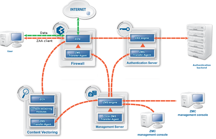
The heart of the PNS–based firewall solution is the firewalling software itself, which is a set of proxy modules acting as application layer gateways. PNS is an application proxy firewall. For details on the architecture of PNS itself, see Section 2.2, The concepts and architecture of PNS firewalls.
PNS must be installed on an Ubuntu-based operating system (Ubuntu 18.04 LTS) which installs automatically when booting from the PNS installation media.
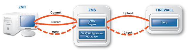
The Management Server (MS) handles the configuration tasks of the entire solution. Your firewall administrators use the Management Console (MC) application on their desktop to access MS and modify the configuration of your firewalls. MS is the central command center of the solution: it stores and manages the configuration of PNS firewall hosts.
The real power of MS surfaces when more than one PNS firewalls have to be administered: instead of configuring the different firewalls individually and manually, you can configure them at a central location with MS, and upload the configuration changes to the firewalls. Because MS stores the configuration of every firewall, you can backup the configuration of your entire firewall system. In case of an emergency, you can restore the configuration of every firewall with a few clicks.
Technically, MS does not communicate directly with the PNS host: all communication is done through the PNS Transfer Agent application, which is responsible for transporting configuration files to the managed hosts, running MS-initiated commands, and reporting the firewall configuration and other related information to MS. The PNS Transfer Agent is automatically installed on every PNS host. The communication is secured using Secure Socket Layer (SSL) encryption. The communicating hosts authenticate each other using certificates. For more information, see Section 13.1.1.5, Configuring authentication settings.
Communication between the agents and MS uses TCP port 1311. If PNS and MS is installed on the same host, communication between the transfer agent and the MS server uses UNIX domain sockets.
| Warning |
|---|
Agent connections must be enabled on every managed host, otherwise MS cannot control the hosts. For details, see Appendix A, Packet Filtering. |
By default, the MS host initiates the communication channel to the agents, but the agents can also be configured to start the communication, if required.
The Management Console (MC) is the graphical interface to Management Server (MS). A single MS engine can manage several different PNS firewalls. MC is designed so that almost all administration tasks of PNS can be accomplished with it and therefore no advanced Linux skills are required to manage the firewall.
| Note |
|---|
|
MC can connect to the MS host remotely, even over the Internet. All connections between MC and MS are SSL-encrypted, and use TCP port MC can only alter configurations stored in the MS database. It does not directly communicate with the firewall hosts. |
MC can be installed on the following platforms:
Microsoft Windows Vista or later
Linux
PNS can authenticate every connection: it is a single sign-on (SSO) authentication point for network connections. During authentication, PNS communicates with the Authentication Agent (AA) application that runs on the client computers.
However, PNS does not have database access for authentication information such as usernames, passwords and access rights. It operates indirectly with the help of authentication backends through an authentication middleware, the Authentication Server (AS). To authenticate a connection, PNS connects to AS, and AS retrieves the necessary information from a user database. AS notifies PNS about the results of the authentication, together with some additional data about the user that can be used for authorization.
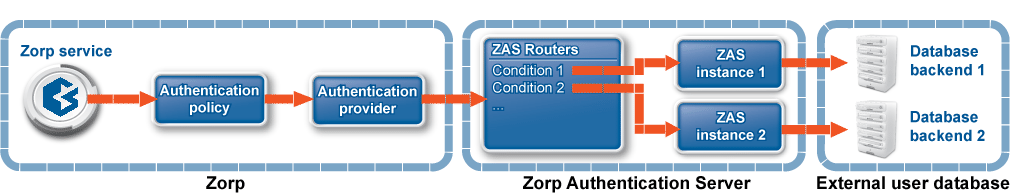
AS supports the following user database backends:
plain file in Apache htpasswd format
Pluggable Authentication Module (PAM) framework
RADIUS server
LDAP server (plain BIND, password authentication, or with own LDAP scheme)
Microsoft ActiveDirectory
AS supports the following authentication methods:
plain password-based authentication
challenge/response method (S/KEY, CryptoCard RB1)
X.509 certificates
Kerberos 5
CF is not a content vectoring engine, it is a framework to manage and configure various third-party content vectoring modules (engines) from a uniform interface. PNS uses these modules to filter the traffic. These modules run independently from PNS. They do not even have to run on the same machines. PNS can send the data to be inspected to these modules, along with configuration parameters appropriate for the scenario. For example, a virus filtering module can be used to inspect all files in the traffic, but different parameters can be used to inspect files in HTTP downloads and e-mail attachments. Also, different scenarios can use a different set of modules for inspecting the traffic. Using the above example, HTTP traffic could be inspected with a virus filter, a content filter, and all client-side scripts could be removed. E-mails could be scanned for viruses using the same virus filtering module (but possibly with stricter settings), and also inspected by a spam filtering module.
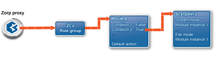
A PNS proxy can send data for further inspection to a CF rule group.
A rule group is used to define a scenario (using a set of router rules).
-
The router rules of the scenario are condition – action pairs that determine how a particular object should be inspected. This decision is based on meta-information about the traffic or objects received from PNS and on information collected by CF.
The condition can be any information that PNS/CF can parse, for example, the client's IP address, the MIME-type of the object, and so on.
The action is either a default action (such as
ACCEPTorREJECT), or a scanpath — a list of content vectoring module instances (the modules and their settings corresponding to the scenario) that will inspect the traffic. Rule groups have a scanpath configured as default, but the routers in the group can select a different scanpath for certain conditions.
The examples demonstrated on Figure 2.5, Content vectoring scenarios in CF can be translated to the CF terms defined in the previous paragraph as follows:
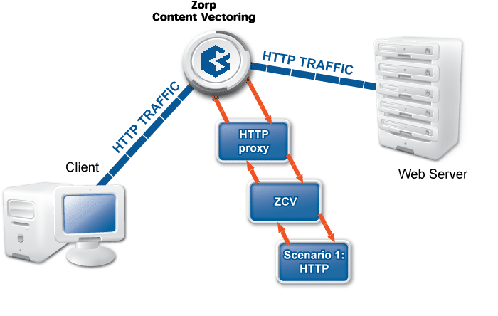
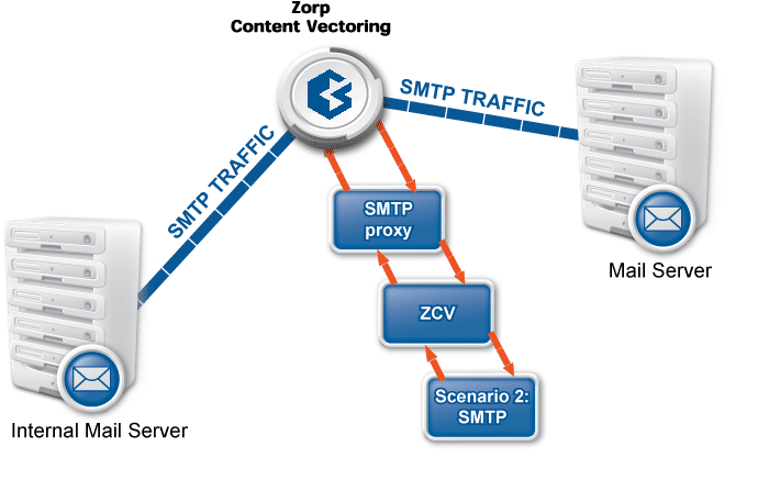
There are two rule groups (scenarios) defined, one for HTTP traffic, one for SMTP.
Router rules in the HTTP rule group call a scanpath.
The scanpath includes module instances of a virus filtering, a content filtering, and an HTML module that are configured to remove all scripts.
This is only a basic example, further router rules could be used to optimize the decisions (for example, there is not much sense in trying to remove client-side scripts in non-HTML files that are downloaded, and so on). Similarly, another rule group corresponds to the SMTP scenario, with a scanpath including a virus filtering and a spam filtering module instance.
The whole process is summarized in the following procedure.
2.1.6.1. Procedure – Content vectoring with CF
A PNS proxy sends the traffic to be inspected to an appropriate CF rule group.
CF evaluates the router conditions of the rule group. If no condition is fulfilled, the action set as default (a default scanpath, or an
ACCEPT/REJECT) is performed. Otherwise, the action/scanpath specified for the condition is followed.The traffic is inspected by the module instances specified in the selected scanpath. A module instance can be used in multiple scanpaths, with different parameters in each one.
The processed traffic is returned to PNS.
The CF framework was designed to allow the easy and fast integration of various third-party content vectoring tools. Currently the following modules are supported:
-
Virus filtering modules:
-
Spam filtering modules:
-
Other modules
HTML filtering module: Capable of general content filtering, as well as filtering JavaScript, ActiveX, Java, and Cascading Style Sheets (CSS).
Mail header filtering: Capable of filtering and manipulating mail headers in SMTP traffic.
Mime filtering: Capable of filtering, removing, and adding MIME headers and objects in HTTP, POP3, and SMTP traffic.
General stream editing module: Capable of replacing strings in data streams.
Custom application: CF provides a general interface to inspect the data with other third-party applications.
Some of the listed modules must be licensed separately from PNS/CF. For details, contact your distributor.
PNS uses strongSwan to support native Linux IPSec solutions, and also supports OpenVPN (an SSL-based VPN solution). PNS supports both transport and tunnel mode VPN channels. Tunnel authentication is possible with X.509 certificates and with pre-shared keys (PSK). IPSec settings can be negotiated manually, or using Internet Key Exchange (IKE).
Native services provide a limited number of server-like features in PNS. Their use is optional and depends on the needs and security requirements of your organization. The use of Network Time Protocol (NTP) and Bind is recommended, while Postfix is useful for managing mail traffic from various firewall components locally.
These services are called native because they are installed with PNS and are available by default. They are implementations of the actual Linux services of the same names. These services provide networking services that are either difficult to implement with application proxies (or at the packet filter level) or provide services for the firewall itself. For more information on these services, see Chapter 9, Native services.
NTP: PNS hosts can function both as a Network Time Protocol (NTP) client and server. Time synchronization among the PNS hosts is very important for correct logging entries. Once the firewall's time is correctly synchronized, it can act as the authentic time source for its internal networks.
DNS: PNS features a fully functional ISC BIND 9 DNS server. It is optional and definitely not mandatory to use if security regulations explicitly prohibit the installation of non-firewall software on the firewall machine. However, in small and mid-sized networks, it can be beneficial to have a built-in name server, if it is solely used as a forward–only DNS server.
SMTP: PNS uses Postfix as the built-in SMTP server component. Postfix is used for SMTP queuing. PNS also has an application proxy for inspecting SMTP traffic, while CF can be used to perform virus, spam, and content-based filtering on the SMTP traffic. The primary role of this Postfix service is to provide a Mail Transport Agent (MTA) for the firewall itself: a number of mail messages can originate from the firewall, and these messages are delivered using the Postfix service. Although the Postfix service is a fully functional MTA in PNS, it is not intended to be a general purpose mail server solution for any organization.
PNS supports multi-node (2+) failover clustering, as well as load balance clusters (most load balance configurations use external devices). Clustering support must be licensed separately. PNS supports the following failover methods:
Transferring the Service IP address
Transferring IP and MAC address
Sending RIP messages
For more information see Chapter 12, Clusters and high availability.
PNS runs on Ubuntu-based operating systems. Currently it supports Ubuntu 18.04 LTS. You can either install the PNS packages on an existing Ubuntu server installation from the official APT repositories, or use our installation media to install a minimal Ubuntu 18.04 LTS server and the PNS packages.
The following sections discuss the main concepts of PNS firewalls.
A firewall controls which networks and hosts can be accessed, and who can access them. To create traffic rules, first you must accurately define the networking environment of PNS, then you can apply access control on the traffic. This can be achieved using zones and rules.
Zones consist of one or more IP subnets that PNS handles together. By default, there is only a single zone: the IP network 0.0.0.0/0, which practically means every available IP addresses (that is, the entire Internet). You can organize zones into a hierarchy to reflect your network, or the structure of your organization.
Although zones consist of IP subnets and/or individual IP addresses, zone organization is independent of the subnetting practices of your organization. For example, you can define a zone that contains the 192.168.7.0/24 subnet and it can have a subzone with IP addresses from the 10.0.0.0/8 range, and the single IP address of 172.16.54.4/32. For details on zones, see Section 6.2, Zones.
The first line of network defense is a packet filter that blocks traffic based on the IP address or TCP/UDP port number of the source (that is, the client) or the destination (that is, the server) of the connection. That way, more thorough analysis, such as traffic inspection or content vectoring is performed only on traffic that is permitted at all. This technology using both packet filtering and application proxying together is called multilayer filtering.
-
Packet filtering: Traffic that can be filtered based on IP and TCP/UDP header information can be blocked at the packet filter level. Likewise, it is possible to forward traffic at the packet filter level without analyzing them with application proxies. For such traffic, PNS operates like an ordinary packet filtering firewall. Forwarding traffic at the packet filter level may be desirable special protocols that cannot be proxied, or if proxying causes performance problems in the connection, or in case of non-TCP/UDP or bulk traffic. PNS provides a number of built-in, protocol-specific proxy classes for the most typical protocols, and it has a generic proxy for protocols not supported by the built-in proxies. Packet filter level forwarding is not recommended, unless it is absolutely unavoidable.
Application proxies provide a higher level of security. Packet filters are the first line of defense, they can be used to block unwanted traffic. What is not blocked by default, on the other hand, should be filtered by the appropriate application proxies.
Traffic proxying: Application level services inspect the traffic on the protocol level (Layer 7 in the OSI model). PNS provides a generic proxy, called PlugProxy that does not perform special data analysis, but can be used to proxy the traffic. Application proxies always provide an additional level of filtering over packet filters.
In PNS, packet filtering is handled by the kzorp kernel module, therefore packet filtering services are completely handled on the kernel level. When PNS starts, it sends all information about the traffic permitted to pass the gateway (that is, the list of configured services, zones, firewall rules, and so on) to the kzorp module.
Application-level services (also called proxy services) are handled on two levels:
The kzorp kernel module receives and accepts the connections.
All other functionality is performed by PNS in the userspace.
For both service types, the kzorp kernel module makes the client-side access control (DAC) decision. Both service types can be configured from a uniform interface using MC.
Handling packet filtering in the kernel has the following important consequences:
Packet filtering rules can match on zones as well, not only on IP addresses.
Network Address Translation (NAT) is available also in the kernel, therefore it is possible to NAT packet filtering services. However, not every type of NatPolicy can be used with packet filtering services. For details, see Section 6.7.5, NAT policies.
The tproxy table of the iptables utility that earlier PNS versions used to perform transparent proxying is empty. PNS does not use it, but it is available if for some reason you want to add rules manually.
PNS is a proxy gateway. It separates the connection between the client and the server into two separate connections: one between the client and PNS, and another between PNS and the server. PNS receives the incoming client connection requests, inspects them, and transfers them to the server. PNS also receives the replies of the server, inspects them, and replies to the client instead of the server. That way PNS has access to the entire network communication between the client and the server, and can enforce protocol standards and the security policy of your organization (for example, permit only specific clients to access the server, or enforce the use of strong encryption algorithms in the connection).
Proxying can take two basic forms:
Nontransparent: In case of nontransparent proxying, client connections target PNS instead of their intended destination.This solution usually requires some client-side setup, for example, to configure the proxy settings in the web browser of the client.
Transparent: To integrate to your network environment easily, PNS can operate transparently. In case of transparent proxying, the client connections target the intended destinations server, and PNS inspects the network traffic directly. The client and the server do not detect that PNS mitigates their communication. In case of transparent proxying, no client side setup is required. This means that you do not have to modify the configuration of your clients and servers when PNS is integrated into your network: PNS is invisible for the end user.
The traffic in a connection usually consists of two parts:
control information (for example, headers and metainformation)
data (the payload)
The protocol proxies of PNS analyze and filter the control part of the traffic, but — in most cases — ignore the payload. (The antivirus and spam-filtering modules of CF inspect the payload.) PNS proxies can thoroughly inspect the protocol headers to ensure compliance to the protocol, disable the use of prohibited options, and so on. PNS can handle commonly used protocols, including:
FTP/FTPS
HTTP/HTTPS
IMAP/IMAPS
NNTP/NNTPS
POP3/POP3S
RDP
SIP
SMTP/SMTPS
SQLNet
SSH
SSL/TLS
Telnet
VNC
Every protocol proxy can handle the SSL/TLS encrypted version of the protocol, and inspect the embedded traffic, giving control over HTTPS, SMTPS, and other connections.
For more information on supported protocols and for a complete list of proxies, see Proxedo Network Security Suite 1.0 Reference Guide.
The default settings of the protocol proxies of PNS ensure that the traffic complies to the relevant RFC for the given protocol. To provide flexibility, and to solve a wide variety of custom scenarios, you can customize the proxies and change their parameters to best suit your environment and your security requirements. For example, you can:
Disable selected commands in FTP.
Modify the transferred headers in HTTP.
Permit using only selected web browsers.
Specify which encryption algorithms are permitted in SSL/TLS.
In addition, the proxies in PNS are fully scriptable, and can be programmed in Python to perform any custom functionality. For information on customizing proxies, see Section 6.6.1, Customizing proxies, and Proxedo Network Security Suite 1.0 Reference Guide.
Today, network traffic often uses more than a single protocol: it embeds another protocol into a transport protocol. For example, HTTPS is HTTP protocol embedded into the Secure Socket Layer (SSL) protocol. SSL encrypts HTTP traffic and many firewalls simply permit encrypted traffic pass without thorough inspection. This is not an optimal solution from a security aspect, and PNS has a better solution to this problem: it decrypts and inspects the SSL traffic, and passes the data stream to an HTTP proxy to inspect it. This modular architecture (that is, proxies can be stacked into each other, or even chained together for sequential protocol analysis) allows for sophisticated inspection of complex traffic, for example, to perform virus filtering in HTTPS, or spam filtering in POP3S traffic.
There are two ways to manage PNS firewalls:
Using the Management Server (MS) and the Management Console (MC) graphical user interface (GUI). PNS and MS are designed to be configured using the Management Console (MC). The Proxedo Network Security Suite 1.0 Administrator Guide focuses primarily on the preferred MC-based administration method.
Manually editing the configuration files of every host. This method requires advanced Linux skills and deep technical knowledge about how PNS works. For more information on this procedure, see Chapter 10, Local firewall administration.
| Note |
|---|
You cannot mix the two administration methods: once you start editing configuration files manually, you cannot continue or revert to using MC, unless you rebuild the configuration from scratch. |
MC itself is just a graphical frontend to MS. It is MS that stores configuration information and manages connections with the agents on managed hosts. The MS-based firewall management can only be performed through MC; there is no console alternative. MC is not “bound” to a particular MS host, as long as the proper username/password pair is known, it can be used to connect to any MS host.
MC can be started the following way:
Windows: Locate the PNS folder in the menu and click on the icon. If no such folder has been created when MC was installed, start
zmc.exemanually from the installation folder.Linux: Start MC from the or menu of your desktop environment, or from the console by executing the following command: ./<installation-directory>/bin/zmc.
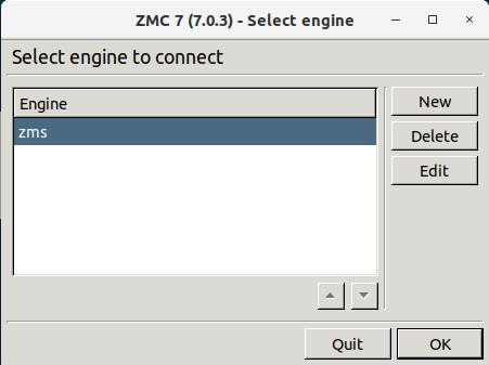
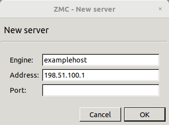
When you first start MC after the installation, the list of reachable MS hosts is empty, therefore you must define a new host. To define a new host, click . MC configurations are stored in a folder named .zmsgui. This folder (for the Windows version of MC) is created in the installing user's profile directory, which is typically %systemroot%\Documents and Settings\%username% The name of the file that stores MC configurations is zmsgui.conf. The Linux version of MC stores configuration information in the same manner, within the user's home directory.
3.1.1. Procedure – Defining a new host and starting MC
Purpose:
To define a new host entry and start MC, complete the following steps.
Steps:
-
To define a new entry in the list of reachable MS hosts, click .
Enter a name for the host in the field. It can be an arbitrary string and does not have be the same as the hostname of the MS Host.
Enter the IP address of the host in the field.
-
Optional step: Fill the field or leave it empty to use the default TCP port
1314.You can change the port assignment later, if needed.
Click . The new entry is now listed in the list.
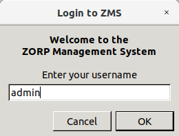
-
To continue with authentication, click .
By default, the built-in administrator account of MS and therefore PNS is
admin. Its MS password was defined during installation.The name of the administrator can be changed or additional administrators can be added later through MC. To modify existing users or add new ones, see Section 13.1.1, Configuring user authentication and privileges. To create user accounts with limited privileges (for example, users who can only look at the configuration for auditing purposes, but cannot change anything) see Section 13.1.1.4, Configuring user privileges.
Expected outcome:
After entering the correct password, if network connectivity is provided, the MC main screen greets you.
| Note |
|---|
When MC connects to a MS engine for the first time, it displays the SSH-style fingerprint of the MS host. During later connections, it checks the fingerprint automatically. |
| Warning |
|---|
MC and the MS to be accessed must have matching version numbers, that is, MS 7.0.1 must be accessed with MC 7.0.1. Login is not permitted if the version number of MS and MS is different. |
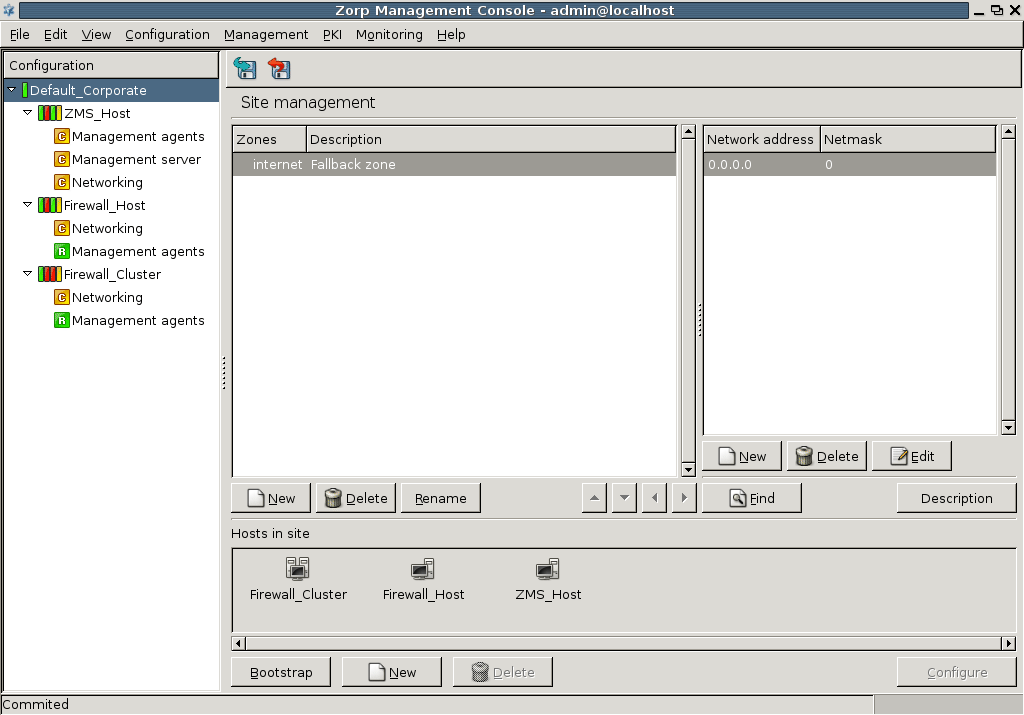
MC is divided into three main parts:
| Note |
|---|
For more information on the configuration buttons of the button bar, see Section 3.3.2, Configuration buttons. |
The following sections introduce MC components and highlight their main purposes.
The configuration tree lists the configurable components of a PNS system. Whenever you select an item in the configuration tree, the main workplace displays the configurable parameters of the selected item. The configuration tree is organized hierarchically and this hierarchy maps the management philosophy of PNS.
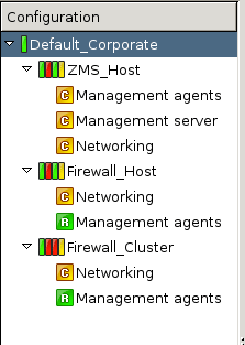
The topmost item in the configuration tree is the 's name that you have entered during MS host installation. There are usually one or more items below it: MS and/or PNS hosts.
In the most basic scenario, where MS is installed on the PNS machine, there is only one machine listed. Note that in this case the name that appears here is the name of the MS host entered during installation. Under each host, a varying number of configuration components are listed.
By default two components are available for each host:
Management agentsNetworking
Because the MS_Host in this example is a Management server too, it has a third component for configuring management server parameters.
Each site, host, and component has status icons or leds on its left. These are described in detail in Section 3.3.6, Status indicator icons.
The number of components increases as you start the real work: many services have standalone configuration components that you have to add to the configuration tree to use them.
The forthcoming chapters deal with these components in detail.
The biggest configuration entity most PNS systems consist of is the . A is a collection of network entities that belong together from a networking aspect.
From the firewall administration point of view, the is the collection of the machine nodes. If the company is large and/or has geographically separated subdivisions, more than one firewall may be required. If they are all administered by a single (team of) administrator(s), they can all fall under the supervision of a single MS host. In this case, the consists of a MS Host and a number of firewalls
The reverse of this setup is not possible: a single PNS firewall cannot be managed by more than one MS hosts, because this setup would cause indefinite and confused firewall states.
If you purchased the High Availability (HA) module for PNS too and therefore have two firewall nodes clustered, they can be administered as a single MS host. Clusters are described in detail in Chapter 12, Clusters and high availability.
MC machines do not belong to the (s) they administer technically, though physically they are located in close proximity to them.
A is a typical container unit and components of a (that is, the s) share only few but important properties:
-
Zone configuration
All s (firewalls) belonging to the same share a common zone configuration. For more information on zones, see Chapter 6, Managing network traffic with PNS.
-
Public key infrastructure (PKI) settings
PNS makes heavy use of PKI, for example, in securing communication between MS and the firewalls, in authenticating IPSec VPN tunnels, proxying SSL-encrypted traffic.
Although a can be managed by a single MS only, a MS can manage more than one sites.
| Tip |
|---|
|
A possible reason for a company to create more than one site may be to maintain different Zone structures for different sets of firewalls. This is a frequent requirement for geographically distributed corporations that have separated network segments defended by PNS firewalls, but want to maintain central (MS-based) control over their firewalls. Another possible user of multi-site, single-MS setups is a support company that performs outsourced PNS administration for a number of clients. In this scenario all business clients are ordered into separate sites, but all these sites are managed by the support company's single MS . |
A is composed of one or more s. s can be the following items:
PNS firewalls,
CF hosts,
AS hosts, and
MS-managed hosts.
At the very minimum setup, when PNS and MS are installed on the same machine, there is one registered for the given . The number of PNS firewall nodes per is only limited by the number of licenses purchased. With the exception of Zone and PKI settings, configuration parameters are always per .
To display system statistics for a component (MS or PNS), click on the name of the . The statistics are displayed under the tab. The following statistics are available:
usage: and
-
Only on PNS hosts:
The version number of PNS
The number and status of running PNS , and
-
The validity and size of the product licenses (PNS, MS, and so on) available on the host. MC displays a warning if a license expires soon, and an alert e-mail can be configured as well. For details on configuring e-mail alerts for license expiry, see Procedure 11.3.8.8, Monitoring licenses and certificates.
Note To access license information from the command line, login to the host and enter:
/usr/lib/zms-transfer-agent/zms_program_status hoststat
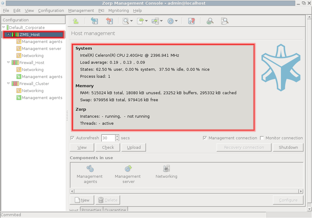
The statistics are automatically refreshed every 30 seconds by default.
| Tip |
|---|
Although host statistics can seem a less important, auxiliary service, it is extremely useful when firewalls operate under continuous heavy load and you want to optimize resource allocation. |
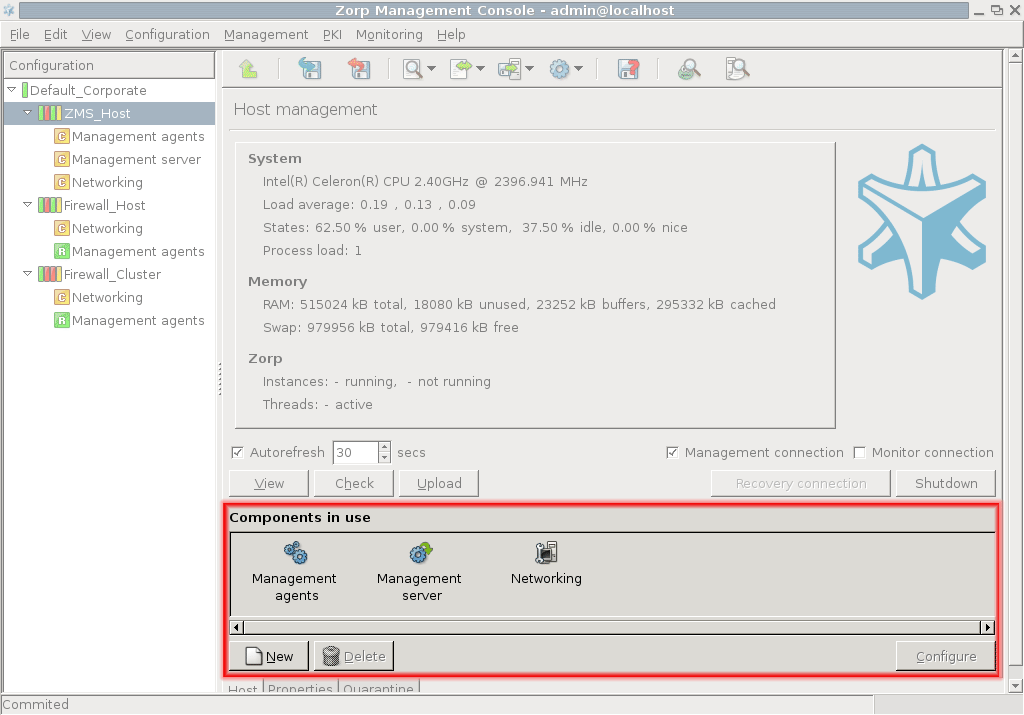
The actual configuration of hosts is performed using configuration components. These components are bound to the specific firewall services. For example, there are separate components for Postfix (), for NTP () and for PNS itself. The list of usable components depend on the type of host under configuration. Most components belong to PNS firewall hosts.
By default, there are two components added for each host: Networking and Management Agent. For MS hosts the Management Server component is added automatically.
3.2.1.3.1. Procedure – Adding new configuration components to host
Purpose:
To add a new confiugration component to a host, complete the following steps.
Steps:
-
Select the host you want to add a new component to in the tree.
Navigate to the tab, and under the section, click .
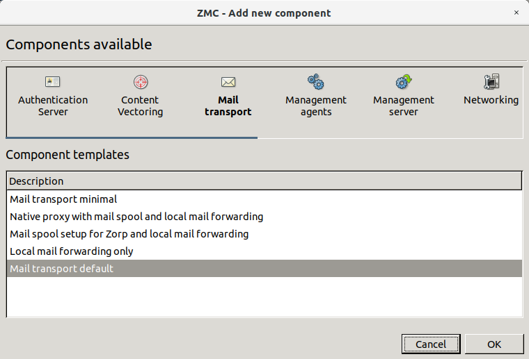
-
Select the configuration component to add from the list.
Note For managing PNS firewall hosts, it is essential to add the
Application-level Gatewayand thePacket Filtercomponents, at the very minimum.The configuration components are strictly focused on the service they manage and all have a distinctive graphical management interface accordingly. For more information on the different components, see the respective chapters.
The following components are available:
: Authentication Server (AS).
: Content Filtering (CF).
: POSTFIX.
:
: Management Server (MS)
:
:
: syslog-ng
:
: NTP
:
:
Select the template to use for the component from the list.
-
Depending on the component, either enter default values for the component in the appearing new window or select a default configuration template.
These built-in templates are configuration skeletons with some default values and options preset. Creating new configuration templates is also possible.
Click .
Most of MC is occupied by the main workspace where you can manage the various components of the tree. The majority of configuration tasks are performed here. The contents of this pane depends on which component you select in the configuration tree.
You can add new administratice components to the host at the bottom part of the main workspace.
If you select a different in the tree, the contents of the main workspace change too.
| Tip |
|---|
The keyboard shortcuts of MC are listed in Appendix B, Keyboard shortcuts in Management Console. |
Although most options of the menu bar are available as buttons on other parts of the MC window, there are some special menu points that have no corresponding button in the main workspace. The buttons are described in the section which deal with the corresponding MC part where they appear.
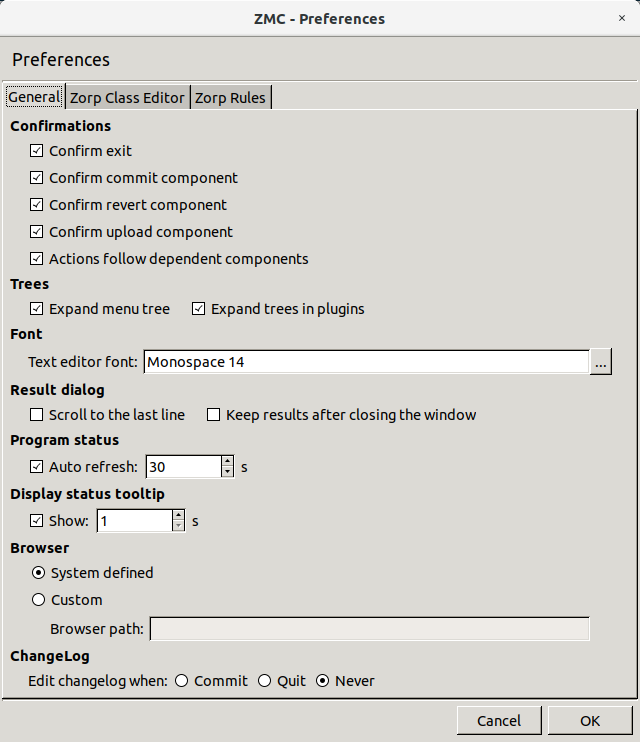
3.2.3.1. Procedure – Configuring general MC preferences
Purpose:
To configure general MC preferences, complete the following steps.
Steps:
-
Navigate to and select the tab.
-
Edit confirmation window preferences in the section.:
To display a confirmation window before quitting MC through or
Ctrl+Q, select .To display a confirmation window before committing
 the configuration changes to a component, select
 To display a confirmation window before reverting
 the configuration changes to a component, select
 To display a confirmation window before uploading
 the configuration changes to a component, select
 and can be combined into a single action, which means that if you want configuration changes to reach the firewall immediately – and not just the MS database – you can do it with a single click. To combine and , select
-
Edit tree-related preferences in the section:
-
Edit text editor font-specific preferences in the section:
To configure the of MC, click
 . Select the font , and the font and click .
 -
Edit result dialog-specific preferences in the section:
-
The status of the interfaces is automatically updated periodically. To configure the update frequency, edit the section:
in seconds.
To turn of auto-refresh, deselect .
-
Edit the length of the delay after status tooltips are displayed when you hover your mouse over a status led or status icon in the section:
Enter the value of the delay in in seconds.
To turn off status tooltips, deselect .
For details on status, see Section 3.3.6, Status indicator icons.
-
Edit browser-specific preferences in the section:
The Proxedo Network Security Suite 1.0 Administrator Guide and Proxedo Network Security Suite 1.0 Reference Guide are automatically installed with MC in HTML format and are accessible from the menu. The guides are opened in the default browser.
To configure a different browser, select and enter in the field the full path name of the browser to use.
Tip The latest version of these guides, as well as additional whitepapers and tutorials are available at the Documentation Page.
-
Edit changelog-specific preferences in the section:
MS now records the history of configuration changes into a log file. The logs include who, when modified which component of the PNS gateway system. Component restarts and other similar activities are also logged, and the administrators can add comments to every action to make auditing easier. By default, MC displays a dialog automatically to comment the changes every time the MS configuration is modified, or a component is stopped, started, or restarted. The changelogs cannot be modified later.
For details on writing changelong comments, see Procedure 3.3.4, Recording and commenting configuration changes.
To configure when MS automatically opens the window, change to:
if you want to automatically open the window after committing
the configuration changes to a component.if you want automatically open the window only before quitting MC through or
Ctrl+Q.if you never want to automatically open the window.
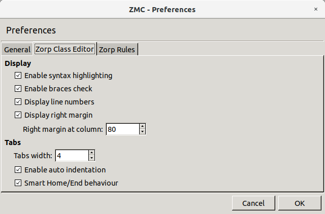
3.2.3.2. Procedure – Configuring PNS Class Editor preferences
Purpose:
To configure PNS Class Editor preferences, complete the following steps.
Steps:
-
Navigate to and select the tab.
-
Configure display-related preferences in the section:
To enable syntax highlighting, select .
To enable syntax validation by checking braces, select .
To display line numbers, select .
To display right margin, select . Enter the column number where you want the right margin line to be displayed in .
-
Configure tabulation in the section:
Enter the indentation width in spaces in the field.
For auto-indentation, select .
For smart behavior for Home and End keys, select .
3.2.3.3. Procedure – Configuring PNS Rules preferences
Purpose:
To configure PNS Rules preferences, complete the following steps.
Steps:
-
Navigate to and select the tab.
-
Configure rule list-related preferences in the section:
To display the complete content of a cell as tooltip, select .
To wrap cell content if it exceeds a certain length, select . Define the .
3.2.3.4. Procedure – Configuring MS hosts
Purpose:
To add, delete or edit MS hosts, complete the following steps.
Steps:
Navigate to .
-
To add a new host, click . For details on the configuration steps, see Procedure 3.1.1, Defining a new host and starting MC.
Note MC cannot connect to more than one MS host simultaneously. After adding a new host, MC will not change to that new host, but will stay logged in to the host that you are currently configuring. To configure the new host, navigate to and login to the new host.
To edit an already existing host, click on the name of the host and click .
-
To delete an already existing host, select the name of the host and click .
Warning There is no confirmation window after clicking , the host is deleted instantly. Make sure that you only click if you want to actually delete a host.
-
Click .
PKI settings are always site-wide and can be configured graphically using the PKI menu only. For more information on PKI usage under PNS, see Chapter 11, Key and certificate management in PNS.
To clarify management it is possible to define system variables for MS. These variables all have a scope, depending on which component is selected in the tree when they are declared.
Altogether, variables can work in three scopes that correspond to configuration levels in the tree: , and .
| Tip |
|---|
Using variables is especially useful in sophisticated, enterprise PNS environments where complex configurations have to be maintained. When referencing variables inside configuration windows, |
By using variables it is simpler and error-free to change a value that is present at many different places. Modifying a corresponding variable results in changed values everywhere they are used.
| Note |
|---|
Instead of variables, you are recommended to use links. |
By default there are two host variables defined:
Hostname, and
autobind-ip.
3.2.3.6.1. Procedure – Defining variables
Steps:
Select a , or in the configuration tree.
Navigate to .
To create a new variable, click .
Enter the - pair in the respective fields.
Click .
3.2.3.6.2. Procedure – Editing variables
Steps:
Select a in the configuration tree.
Navigate to .
To edit a variable, select the variable and click .
Enter the new - pair in the respective fields.
Click .
3.2.3.6.3. Procedure – Deleting variables
Steps:
Select a in the configuration tree.
Navigate to .
-
To delete a variable, select the variable and click .
Warning There is no confirmation window after clicking , the variable is deleted instantly. Make sure that you only click if you want to actually delete a variable.
Click .
The bottom line of MC is called the status bar. When working with configuration components it can be used to check whether changes have already been or there are . By checking the status, you can determine whether what you see on the MC interface is the same as the information currently stored in the MS configuration database (committed status) or not.

Most configuration tasks concerning PNS are component–based and even those that are site-wide, such as Zone manipulation, must be individually uploaded to all firewalls of the given site. Therefore, configuration tasks can be organized into cycles and most elements of these cycles are the same regardless of the component that is configured. In fact, most of the configuration is repetitive and therefore can easily be procedurized.
In this section, after a brief overview of the most typical steps, the configuration process and the tools (buttons) that are used to perform each task are presented.
When you login to MS through MC, first an SSL encrypted channel is built, then firewall configurations currently stored in the MS database are downloaded into MC. When you finish doing configuration changes they are committed back into the MS database. At this point no changes are made to the firewall(s); only the database on the MS host is modified. It takes a separate action, an upload issued to actually propagate changes from the database down to the firewall(s). With this upload action the configuration changes get integrated into the configuration files on the PNS machine(s). For final activation, a reload or restart (depending on the situation and the service being modified) is needed to activate the changes.
A complete configuration cycle consists of the following steps.
3.3.1.1. Procedure – Configuring PNS - the general process
Select the component that you want to configure in the tree.
Perform the actual configuration changes on the component. For details, see the relevant chapters.
-
Commit
changes to the XML database of MS. Otherwise, the changes are lost when you navigate to another component.Write a brief summary about the changes into the . For details, see Procedure 3.3.4, Recording and commenting configuration changes.
To activate the changes, upload
them to the affected PNS firewall hosts from the MS database. MS converts the changes to the proper configuration file format and sends them to the transfer agents on the firewall nodes. The changes are applied on the firewall nodes.Reload the altered configurations on the firewalls, or restart the corresponding services.
| Note |
|---|
Not all of these steps are performed in each configuration cycle. Service reloads or restarts are typically postponed as long as possible and are likely to be performed only after all configuration tasks with the various service components are finished. |
Most administration commands for the configuration tasks can be issued from either the menus or the buttons in the Button bar. The number of buttons visible varies based on the component that you have selected in the tree.

The
and
buttons are always visible, at the minimum.
is used when you finish a (set of) configuration changes and want zo save these changes to the XML database of MS.
serves the opposite purpose: before committing changes to the MS database, it is possible to clear, to undo them in MC.
| Note |
|---|
It is very important to remember that is limited to MC, it cannot clear configuration changes that are already committed to the MS database. Those changes can be undone by performing a new round of changes in MC and then committing these changes again. |
Both and are component–focused controls. This means that before you select another component from the tree, you must commit the changes in the current component, otherwise they are lost. In such cases, MC displays the following warning:

is used to upload the configuration changes committed to the configuration database on the MS Host further to the corresponding PNS firewall(s).
| Tip |
|---|
and can be combined into a single action, which means that if you want configuration changes to reach the firewall immediately – and not just the MS database – you can do it with a single click. To combine and , navigate to and select . |
 Under , you can or services so that they re-read the new configuration files that are already on the corresponding PNS firewalls after a successful / cycle.
ing or ing the given service depends on the type of service (some cannot be reloaded, only restarted) and the intended outcome.
After clicking , the following actions are available:
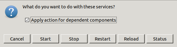
| Note |
|---|
Besides and , there are also and functions available here to start or stop services. |
 and
and
 are both used to retrieve information on the current state of the PNS firewall(s).
displays the configurations of the component selected in the tree on the selected host. This information comes from the MS configuration database, which is not necessarily the same as the actual settings on the selected host – when changes are already committed, but not yet uploaded. For example, if you select the MS_Host > Networking component and then click , you will see the following:
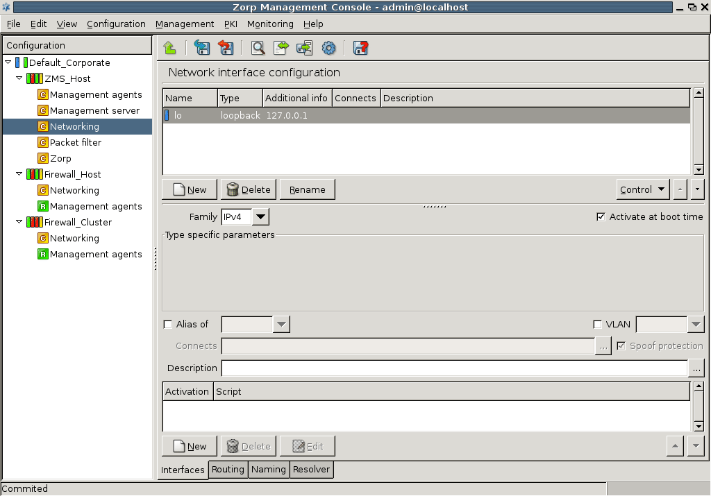
It is a file-by-file listing of the active configuration on the selected host. Note that it is not necessarily the same configuration that is stored in the MS database: after a commit but prior to an upload event they can differ significantly. To query this difference, click . Using the Linux diff utility by default, it compares configurations stored in the MS database with the configurations currently active on the selected host.
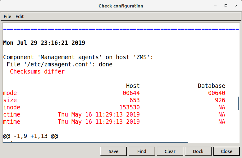
The differences are marked in red, otherwise you see the normal output of diff, with + and – signs designating data from the host and from the database, respectively. The diff command can be replaced with another utility of your choice under the Management Server component. For details, see Chapter 13, Advanced MS and Agent configuration.
Configuration files:
 provides further information and configuration options of the files and attributes described in the output window of and the diff command.
serves two purposes.: It provides vital information about which configuration files a component (of the tree) uses and gives chance to modify the properties of the listed files.
For example, in case of the Networking component, the list of used files is the following.
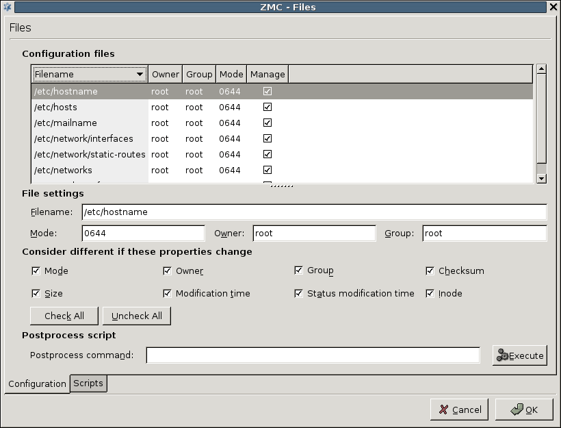
Apart from the name and location of files, you can retrieve information about owner, owner group, access rights and file type parameters. The column is very important and has a corresponding checkbox immediately below the file listing: this can be used to control what files MS manipulates on the host machine, if needed.
| Note |
|---|
It is not recommended to take files out of the authority of MS, because it can severely limit the effectiveness of MS–based administration. However, it is possible to do it, if you deselect the checkbox under the column. |
File settings:
To modify the properties of a file, click on the file in the list. The following subwindow opens.
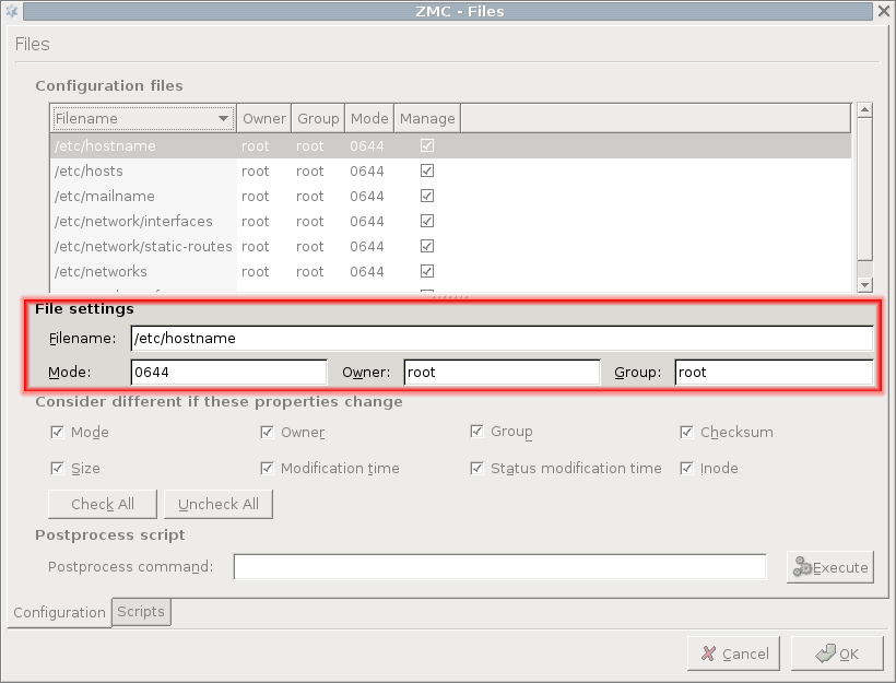
| Warning |
|---|
There must be a solid reason for changing these properties and you must be prepared for the possible consequences of such actions. A good understanding of Linux is recommended before making changes in file properties. |
Consider different if these properties change:
The third part of the window is for configuring the work of the comparison utility, which is diff by default. You can define what file properties you are interested in when checking for changes.
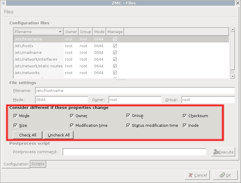
| Tip |
|---|
Checking for configuration file differences is beneficial from a security aspect too: it is an additional tool for making sure nobody has altered critical files on the firewall. |
Postprocess script:
At the bottom of the tab, you can specify a postprocess command that is run after the corresponding configuration file is uploaded to the firewall host. Some services rely heavily on this option. For example, Postfix that runs / usr/sbin/postmap %f as a postprocess command to transport virtual domains and set various access restrictions are properly.
Scripts tab:
Configuration files under Linux are re-read during service reloads or restarts. These actions are performed by running the corresponding scripts exclusively from the /etc/init.d directory. The tab of the window provides an interface where you can check starting scripts and alter and fine-tune them with special Pre upload and Post upload commands. With simple components, such as Networking, these options are rarely used, but in some cases might prove especially useful.
Some components, for example, , can manage configuration files that are automatically reloaded. They cannot be restarted after a . To set the status icon of these components to , select on the tab.
Some components are related to or dependent upon each other, meaning that modifying one modifies the other too. If modifying a component affects another component, the status of this related component changes to in the tree. MC automatically handles related components and all actions (, , and so on). Just select the checkbox in the confirmation dialog of the action.
When reloading or restarting a component related to the Packet Filter, the skeleton of the Packet Filter is automatically regenerated. See Appendix A, Packet Filtering for details on generating skeletons.
3.3.4. Procedure – Recording and commenting configuration changes
Purpose:
MS now records the history of configuration changes into a log file. The logs include who, when modified which component of the PNS gateway system. Component restarts and other similar activities are also logged, and the administrators can add comments to every action to make auditing easier. By default, MC displays a dialog automatically to comment the changes every time the MS configuration is modified, or a component is stopped, started, or restarted. The changelogs cannot be modified later.
The behavior of the changelog window can be configured in . For details, see Procedure 3.2.3.1, Configuring general MC preferences.
To review the existing changelog entries, navigate to . The window contains two filter bars: the filters for changelog entries, the filters inside a single changelog entry, if it contains too many actions. For details, see Section 3.3.10, Filtering list entries.
Steps:
Optional step: If the window is not configured to display automatically after committing or quitting, you can add a new changelog entry manually. To do this, navigate to .
-
Review the details of the changelog entry. Every changelog entry includes the following information:
: The date when the action was performed.
: The MC username of the administrator who performed the action.
: The PNS affected by the action.
: The MC components affected by the action.
: The type of change that was performed.
-
Enter the following:
: Enter a short summary of the changes.
: Enter a detailed description of the changes.
To save the changelog entry, click .
Most firewalls are administered by a group of administrators and not just by a single individual. In a PNS system each administrator can have their own MC console and administrators can be separated geographically. Regardless of their locations they administer the same set of PNS firewalls through a single MS host machine. Therefore, to avoid configuration errors caused by more than one administrator working with the same component simultaneously, a configuration lock mechanism ensures that a component's configuration can only be modified by a single administrator at a given time. Locking is per component: as soon as you change, for example, a setting in a component, the status bar displays the following string: and that component is locked for you. Active locks can be viewed at :
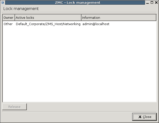
The column can take two values:
-
meaning that someone else is working with the given component
-
indicating your own locks.
Lock placement is automatic. The first administrator that starts modifying a component's settings gets the lock. In the column the exact name of the locked component (//) is displayed. Locks are cooperative, meaning that any administrator can release any other administrator's locks by selecting the desired component in the window and then clicking . The administrator whose lock is released this way is immediately notified in a warning dialog.
| Note |
|---|
Because this is a rather radical interaction, concurrent administrators should discuss lock situations before possibly devastating each other's work. |
It is not possible to edit a component that is already locked by someone else, because a warning dialog immediately appears upon trying to change anything inside the given component:
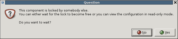
As soon as the locking administrator commits the changes, the lock is released and the information box above disappears.
A component can be locked by multiple administrators at once; there is a lock queue mechanism implemented in MS, meaning administrators can preregister for future locks while the current lock is active. Since there is no hierarchy among PNS administrators from MS's aspect and anyone can release anyone else's locks, it is crucial for administrators to cooperate well and respect each other's work – and each other's locks.
The tree in MC displays various indicators to provide a quick overview about the status of the managed sites, hosts, and components. and -level status is indicated by leds, while icons are used to display -level status information.
Hovering the mouse cursor over a led or icon displays a tooltip with the full description of the status.
| Tip |
|---|
Status tooltips are displayed for the period configured in (for details, see Section 3.2.3, Menu & status bars and Preferences). It is also possible to disable the tooltips altogether. |
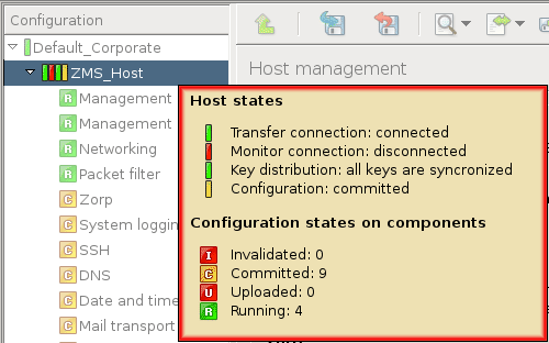
| Note |
|---|
Similar leds are also used throughout MC to display information about the state of various objects, for example, network interfaces, PNS instances, NTP servers, Heartbeat resources, and so on. These are described in their respective sections. |
The -level led displays the validity of the certificates used by the PKI system of the (for details, see Chapter 11, Key and certificate management in PNS). The led has the following three different states:
Green
 : All certificates are valid.
Yellow
 : One or more certificate will expire soon.
-
Red
 : One or more certificate has expired.
Note Expired or soon-to-expire certificates are displayed in bold on in the PKI management tabs.
The status of the is displayed by four different leds. From left to right, these are the following:
All four leds can be ,  , indicating a partial or unknown status: this appears when the status of the nodes of a cluster differs from each other. For example, the transfer agent led is blue if the agent could establish the connection to only one of the nodes, or if the state of the agent is unknown.
Hovering the mouse pointer above the leds displays a tooltip containing detailed information of the leds, including a summary of the committed/uploaded/and so on components.
These leds indicate the status of the Transfer and Monitoring agent connections, respectively.
- : the agent is connected to the host.
- : a connection attempt is in progress.
- : the agent is disconnected.
The management connection leds display unknown status if the given connection is not enabled on the host and is in the disconnected state.
This led indicates the availability of the required certificates and keys on the .
- : normal state.
- : the certificates have been modified (for example, refreshed), but the new certificates have not been distributed yet to the .
| Warning |
|---|
This status led is especially important, because if the certificates are not distributed properly, MS will not be able to communicate with the . For details on distributing certificates, see Section 11.3.5.2, Distribution of certificates. |
The status of each component on a host (or cluster) is indicated by a single icon. The components can have the following state:
Modified  : The component has been modified, but the changes have not been commited to the MS database yet.
Invalidated  : This status indicates that the component has to be updated because of a modification that was performed in another component. For example, committing modifications of the component invalidates the component, because the packet filtering rules have to be regenerated. Invalidated components automatically become modified when they are selected from the tree.
Committed  : The modifications of the component have been saved to the MS database, but the new configuration has not been uploaded to the host. For details, see Section 3.3.2.1, Commit and Revert.
Uploaded  : The new configuration has been successfully uploaded to the host. For details, see Section 3.3.2.2, Upload current configuration.
Running  : The uploaded configuration has been successfully activated on the host (for example, the service/instance has been restarted/reloaded, and so on). For details, see Section 3.3.2.3, Control service.
Partial 
 : These states appear when the status of the nodes in a cluster differs from each other. For example, the partial uploaded icon indicates that the new configuration was not successfully uploaded to all nodes.
Locked: The component is in use (and has been modified) by another user (for details, see Section 3.3.5, Multiple access and lock management). This status is indicated by the above icons having grayed colors, for example,  .
.
Occassionally it might be required to manually modify the status of a component. This can be done from the menu through the and menu items.
| Note |
|---|
Only uploaded components can be marked as running. |
MC provides two graphical aids that can help administration when parts of a host's configuration settings have to be recreated on another host.
-
Copy-paste
Elements of the configuration (for example, network interfaces, proxies, policies, and so on) can be copied and then pasted to another host. This method can also duplicate an element on the same host. All settings of the element are copied to the target host.
To copy a configuration element, select the file content for example, right-click and select .
To paste a configuration element, right-click where you want to paste the element and select .
Warning Make sure to verify the settings of the pasted element, especially the parameters that used links.
-
Multiple select
To select consecutive multiple components, select the first component, press Shift and click the last component.
To select multiple components that are not consecutive, select the first component, press Ctrl and click the next component that you want to select.
If you select multiple components, after right-clicking, the , , and operations are permitted. After clicking one of the options, all configuration files are batch-processed.
Additionally, a program, for example an archiving script, can be run on the configuration files of all selected components. To do this, either select the command from the drop-down menu or enter the command in the field and click .
Note Multiple selected components can also be copy-pasted.
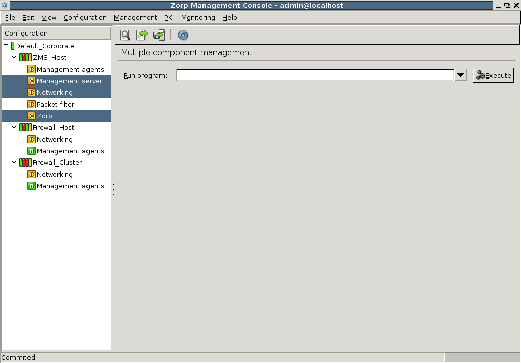
You have two options to refer to components involved in network configurations.
Create links
Use variables
If you use links, you can manually enter IP addresses or select the link target from a drop-down menu. Using links has the advantage that future changes in the network setup does not influence the operability of the connection.
You can delete the existing links with the and options.
ceases the link connection totally, meaning that the link field is left empty.
deletes the link but leaves the target IP address in the field which will then behave as a manually added address.
You can refer to components with variables. By using variables you change values appearing in several places at once. If you modify a variable, all corresponding values are changed. Variables are denoted with $ characters preceding and following their names.
During the management and maintenance of the firewall host it is often useful to be able to temporarily turn off certain rules, policies, and so on. In PNS this feature is implemented through the / options of the local menus. To display the local menu of a rule or object, right-clicking on the object. For example, a packet filter rule that is only rarely used can be simply disabled when it is not required, to be enabled again when it is required. Disabled rules and objects are generated into the configuration file as comments with the # prefix.
Disabled objects can be edited, modified similarly to any other object. However, their validity (for example, the required parameters are filled, their name is unique, and so on) is checked only when they are enabled again.
The following objects can be disabled in the various MC components:
Host:
Disabling a group automatically disables its childrens as well.
| Note |
|---|
Generated rules do not remain disabled after skeleton generation. |
(including matchers)
AS:
Heartbeat:
IPSec VPN:
MC displays information in several places as tables of entries having various parameters or meta-information. Such filter windows are used to display firewall rules, Application-level Gateway logs, active connections, and so on. The common properties and handling of these tables is summarized in this section.
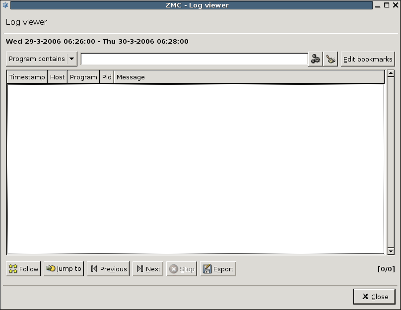
Filter windows consist of three main parts:
Filter bar
Table displaying the entries
Command bar to perform various actions on the selected entries
The actions available in the command bar are described at the documentation of the actual component using the filter window (for example, Log viewer).
Each entry of the table consist of a single row, with the various parameters displayed in labeled columns.
To sort the entries, click on the column headers.
To modify the order of the columns, drag the column header to its desired place.
To hide a single column, right-click on the column header and click .
To configure the columns to be displayed, right-click on the column header and click , select a column and move it with the arrow. Click .
To filter the entries, use the filter bar located above the table. The specifies the column to search for the expression (string or regular expression) that you type in the field. To search, click . To restore the full list, click . To create custom filter expressions, selecting the option as . The filter expressions can also be combined using the logical AND () and OR () operations. You can run custom filters once (click ), or you can bookmark them for repeated use (click ).
| Tip |
|---|
To display the dialog with the latest advanced filter, click . |
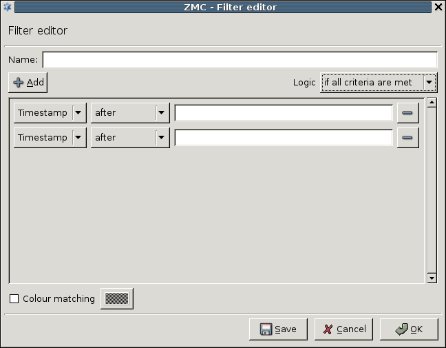
Saved filters are also displayed in the combobox. To manage saved filters (delete, rename and edit), click .
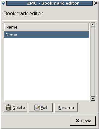
In some cases (for example, in the Log viewer), you can configure advanced filters to highlight the entries matching the filter expression. To configure highlighting, select and set the color of the highlighting.
| Tip |
|---|
By assigning different colors to different bookmarked filters, the important elements of the table can be highlighted in several colors. |
provides an interface for inspecting the log messages collected on a host. To view the logs of a host, select the and click  .
.
| Tip |
|---|
PNS can also create reports about the transferred traffic. For details, see Section 6.9, Traffic reports. |
The log viewer interface consists of a filter bar to select the messages to be displayed a list of the actual log entries (including meta-information such as timestamp, and so on), and a command bar.
The following information is displayed about the messages:
: The exact date when the message was received.
: The host sending the message.
: The application sending the message (for example, cron, zms-engine, and so on).
: The Process ID of the application sending the message.
: The message itself.
The window is a Filter window. Therefore, you can use various simple and advanced filtering expressions to display only the required information. For details on the use and capabilities of Filter windows, see Section 3.3.10, Filtering list entries.
The command bar offers various operations to display and export the logs of the host. The following operations are available:
: Start the follow mode and monitor the log messages real-time. The list is updated every second.
-
: Select a time interval and display the log messages received within this interval. To specify an interval, enter its and , and either both and , or the . Enter the name of the log file in the field.
: Display the log messages of the previous period (using the same interval length).
: Display the log messages of the next period (using the same interval length).
: Stop the mode.
: Export the currently displayed log messages into a file on the local machine that is running MC, using either plain text or
CSVfile format.: The rightmost combobox selects the type of messages that are displayed (for example,
zms,packet filter, and so on).
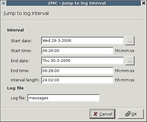
PNS and MS can be used in several network scenarios. In the simplest case there is only a single firewall host having both PNS and MS services installed. In this case the communication between MS and the PNS management agents takes place locally, using Unix domain sockets and it does not require network communication setup. However, when the two functions, that is, firewalling and management, are separated and installed on two different machines, the initial communication channel between the two requires manual setup. After successful setup all further communication is initiated automatically without manual interaction. This channel setup is a one-time action, therefore it must be configured separately for each new PNS firewall under the authority of a MS host. This process is called bootstrapping and can be performed similarly to running a wizard. By the end of the bootstrapping process the new host is added to the host configuration database of the MS host machine.
The connection between MS and PNS can be established in the following ways.
Using bootstrap
Manually through the function
Completely manually
Bootstrapping a PNS host is one of the most simple methods. Bootstrapping is similar to running a wizard, that is, answering questions and allowing the wizard to carry out the necessary configurations. Alternatively, the connection can be established manually. This method may especially be needed in troubleshooting scenarios with the help of the button. Hosts can be added on a completely manual way, by selecting a site and then clicking in the main workspace. For more details, see the PNS Reference Guide.
4.1. Procedure – Bootstrap a new host
Purpose:
To bootsgrap a new host, complete the following steps.
Steps:
Select the desired site in the configuration tree.
-
Click at the bottom of the screen. This will start the wizard.
Note Alternatively, to register a host manually, click next to .
-
Select a host template.
The default templates are the following. New templates can be created later.
-
To configure clustered solutions.
-
To add the , and components automatically to the tree under the name of the newly added host.
For details, see:
-
To add only the two default components: and .
It is recommended to select the because it alredy has some components pre-configured.
Tip If you work with several PNS hosts it can be useful to create predefined templates, to save repetitive work. For details on creating templates manually, see Chapter 6, Managing network traffic with PNS.
-
-
Enter the details of the new host.
: the name of your PNS firewall.
: The name of the component.
: The name of the component.
: The name of the component.
: The name of the component.
: Specify a time server that PNS synchronizes its system time with. Usually, but not necessarily it is an external time source. For the up-to-date list of publicly available time servers, see http://support.ntp.org/bin/view/Servers/WebHome. For more information on NTP, see Chapter 9, Native services.
: The name of the component.
: The name of the component.
-
Enter the IP address and configuration port number of the Transfer agent.
Before you start, discover which network interface and IP address is reachable from your network location. Firewalls almost always have more than one of these. Ensure that the IP address you type in is reachable from your location and that packets will find their way back from the firewall. In other words, make sure that all routing information is correctly configured.
You can configure other interfaces of PNS to be reachable for configuration purposes later.
-
Enter the .
Refer to the Firewall's installation documentation for the IP address information.
Leave the field default (
1311.
-
-
Create a certificate for SSL communication establishment
Firewalls are administered from a protected, inside interface and while this method is highly recommended, it is not necessarily required. All the configuration traffic is encrypted, using SSL.
The administrative connection is encrypted using SSL, which requires a certificate, especially the public key it contains. This certificate and the private key used for encryption/decryption are sent to the Management agent on the firewall node that uses it to encrypt the session key it generates. For more information on SSL communication establishment, see Chapter 11, Key and certificate management in PNS.
Enter the parameters of the certificate and it will be generated automatically.
-
To , enter a name for the certificate in the field. Alternatively, to , browse for a certificate from . The following steps describe the details of creating a new certificate.
Tip There are no particular requirements for the and fields other than trivial string length and restricted character issues. However, it is recommended to enter a name that will later — when there are more certificates in use in your system — uniquely and easily identify this certificate as the one used for establishing agent communication.
In the field, enter the two-character country code of the country where PNS is located. For example, to refer to the United States, enter
US.Optional step: In the field, enter the state where PNS is located, if applicable. For example,
California.In the field, enter the name of the city where PNS is located. For example,
New York.In the field, enter the name of the company that owns PNS. For example,
Example Inc..In the field, enter the department of the company that administers PNS. For example,
IT Security.-
Enter a that describes you or your subdivision.
Alternatively, you can use the default value: the name of your PNS firewall node.
-
Configure the RSA algorithm. Select whether to use
SHA-256orSHA-512. Select the asymmetric key length from the list.Note The U.S. National Institute for Standards and Technology (NIST) recommends
2048-bit keys for RSA. -
Configure the validity range of the certificate.
To select the start date from the field, click
.To configure the validity range, either select the end date from the field by clicking
or enter the validity in days and press Enter.
-
-
Enter MS Agent CA password.
Manually entered passwords protect private keys against possible unauthorized access. Even if an attacker has read access to your hosts, your private keys cannot be stolen (read). These passwords are used to encrypt the private keys and therefore they are never stored in unencrypted format at all. Certificates are issued by Certificate Authorities (CA) and it is actually the CA's private key that requires this protection. The certificate used by the Management agents are issued by the MS_Agent_CA. You have to enter the password for this CA that you defined for this purpose when installing MS service. See also Chapter 11, Key and certificate management in PNS.
Note To generage a strong password, it is recommended to use a password generator.
Tip Take detailed logs of the installation process, including the bootstraps where all these passwords are recorded.
-
Enter the One-Time Password.
The is the one that you have entered during the installation of zms-transfer-agent on the PNS host. It is a one-time operation: to establish an SSL channel between the Management agents of PNS and the MS host, certificates are required. Yet there are no certificates to use, therefore you have to provide the zms-transfer-agent on PNS a certificate to use for communication channel buildup purposes. This password is used to establish a preliminary encrypted communication channel between PNS and the MS host, where the certificate can be sent. All communication among the parties is performed using SSL.
-
Click the final button if all password phases were successful to build up the connection.
The displayed logs provide information about the steps the wizard takes in the background. To save the output for later analysis if needed (either by you or support personnel), click .
Note If anything goes wrong the wizard takes you back to the window you made a mistake in, so that you can correct it.
After the bootstrap process has finished successfully, the new host is ready to be configured.
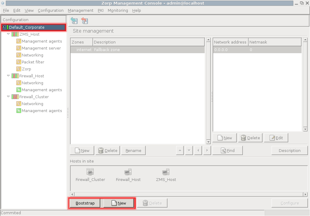
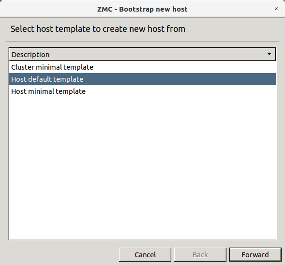
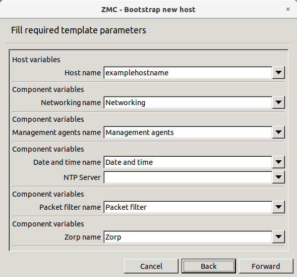
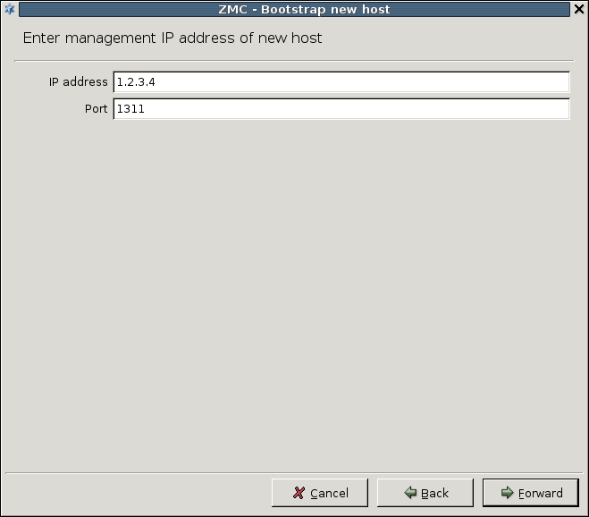
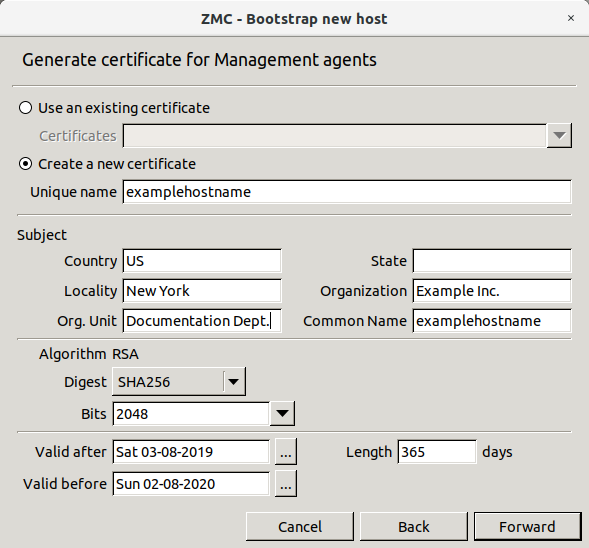
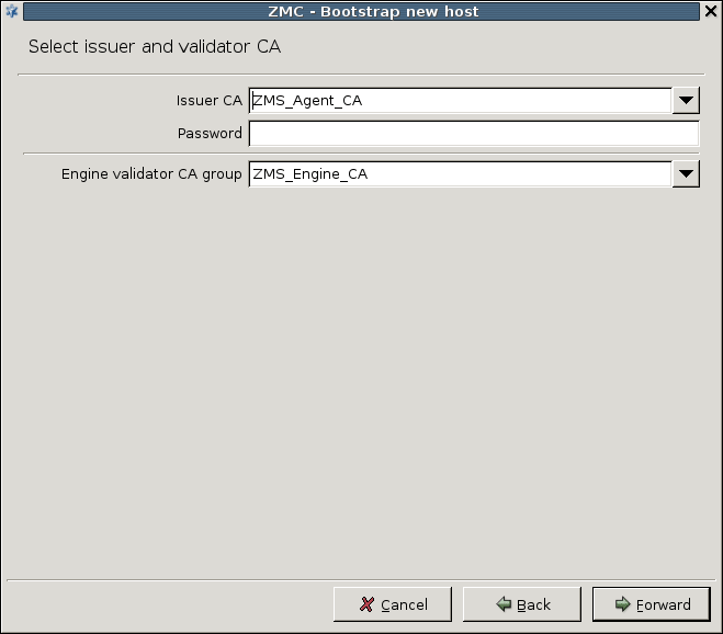
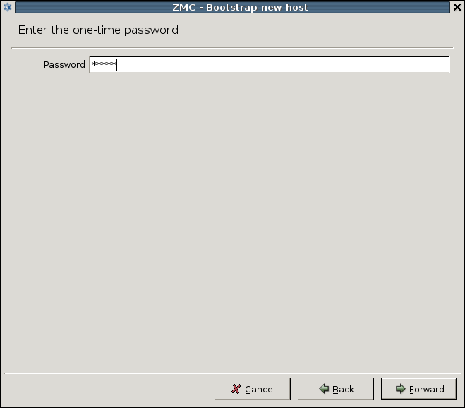
When you start up MC and select a host in the tree, the connection with the host is automatically established. If, for some reason it breaks, you have to reconnect the host manually.
4.2.1. Procedure – Reconnecting MS to a host
-
Navigate to .
This window accurately shows that it is not the PNS host that directly communicates with MS, but the Management agent installed on it.
Agents are responsible for reporting firewall configuration and related information to the MS and are also responsible for accepting and executing configuration commands. Communication between the Transfer Agent and MS uses TCP port
1311. The Transfer Agent must be installed on all firewall nodes to be managed with MS. By default, MS establishes the communication channel with the agents, but the agents can also be configured to start the communication if required. Connect and/or disconnect the appropriate agents with the corresponding buttons.
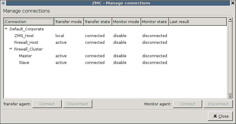
MS is a complex central management facility for PNS firewalls. Besides firewall-centric configuration settings, such as firewall policies, packet filter rules, it allows for the configuration of several basic parts of the operating system. In fact, one of the design goals of MS was to eliminate the need for command-line configuration of the operating system and PNS as much as possible. Therefore tools are provided to perform basic, operating system–level configuration tasks.
The component that is present by default for each host in the tree serves this purpose by providing access to all the relevant network–related configuration areas of the host's operating system. The possible settings in the component are mostly related to ordinary network configuration issues and there are hardly any variables directly related to firewalling functions.
The main window of the component is divided into the following four tabs.
Interfaces tab for configuring general interface-related settings
Routing tab for managing network routes
Naming tab for configuring name resolution
Resolving tab for configuring client-side DNS resolution
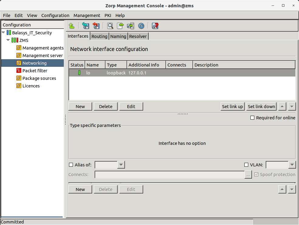
The configuration of network interfaces can be performed on the tab of the MC component. These tasks fall into the following categories.
General and special interface configuration features are available for every host managed from MS, while spoof protection is intended for PNS gateways or other hosts that have an active packet filter installed.
The tab of the MC component lists the network interfaces available on the host, along with their type, IP addresses, and connected zones.
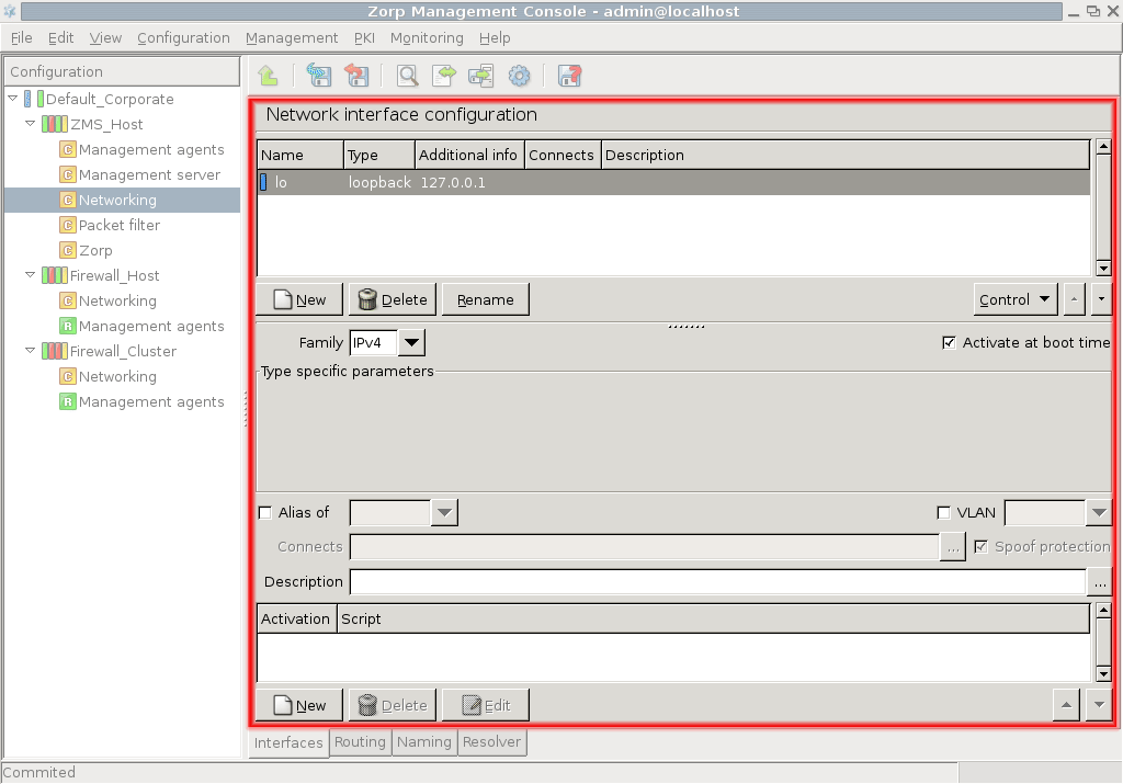
| Tip |
|---|
|
If you do not see one or more physical interfaces of your host listed here, it is most likely because they were not configured before bootstrapping took place. The bootstrapping process not only establishes the connection between MS and the host (Management agents on it), but it also queries host configuration and inserts this information into the MS database. When selecting a host entry in MC, the information is read from the MS database, and not from the host directly. Therefore, MC does not detect parameters that were unavailable for MS during bootstrapping. To correct this situation, define the missing interface(s): click and configure them as required. |
5.1.1.1. Procedure – Configuring a new interface
Purpose:
To define a new interface, complete the following steps.
Steps:
Navigate to tab.
Click .
In the field, enter a name for the interface (for example,
eth0).-
Select the of the interface.
Optional step: Enter a description, if you want to. To enter a longer description, click
.Click .
-
Configure the parameters of the interface below the table: enter the IP , , and other data as required. The list of type-specific parameters depend on the type of interface you are configuring.
For static interfaces, that is, regular Ethernet interfaces enter the
Netmaskparameter using the CIDR notation.Warning As with all firewalls, you can specify only one gateway address in the network configuration and only for a single interface. The gateway box for all other interfaces must be empty.
Note If the configuration information you enter in MC is not the same as the current settings on the host, the settings of the host are overwritten during the next action.
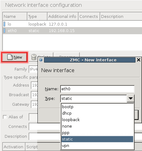
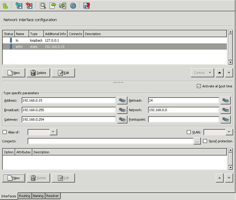
If you change interface settings, To activate the changes, you have to restart the modified network interface. Additionally, it may be required to temporarily stop an interface for security or maintenance reasons with the button under the network interface listing.
| Warning |
|---|
Restarting the interface might terminate all ongoing connections of the interface. |
| Note |
|---|
The interfaces are controlled individually. |
Dynamic interfaces are interfaces that are either created dynamically, or obtain IP configuration information dynamically from a designated server (for example, dhcp, bootp, ppp). Because their IP configuration is not known when PNS boots up (and can be different at each boot sequence), the services using these interfaces cannot include the IP address of the interface in the firewall rules related to the service. To overcome this problem, PNS can bind to interfaces instead of IP addresses. Dynamic interfaces are referenced by their name in the firewall rules. The operating system automatically notifies the running PNS instances when the IP configuration information of the interface is received from the server. IP address changes are also automatically handled within PNS. For more information on configuring firewall rules, see Section 6.5, Configuring firewall rules.
In some cases it can be useful to fine-tune the network for special purposes. For example for Virtual Local Area Network (VLAN) technology: many organizations use it for security and network traffic separation purposes. VLANs are logically separated components of physical networks. Logical separation means that although they are on the same physical network (otherwise known as broadcast domain) hosts on separate VLANs cannot communicate with each other unless a router is set up that provides the interconnection. Routing functions for VLAN, and VLAN creation in general, are typically performed by Layer 3 Ethernet switches. Provided that VLAN-capable network cards are installed in the machine, PNS fully supports VLANs and MS provides a control for configuring it.
VLAN interfaces are named in the following manner:
ethx.n where
- x
is the number of the physical interface
- n
is the ID of the VLAN. The ID of the VLAN is usually a number (for example,
0for the first VLAN of the interface,1for the second, and so on)
| Note |
|---|
|
If you define an interface as a VLAN interface, it cannot operate as a real, physical interface at the same time. For example, the |
5.1.2.1. Procedure – Creating a VLAN interface
Purpose:
To create a VLAN interface, complete the following steps.
Steps:
-
Every VLAN interface must be connected to a physical interface. If not already configured, configure the physical interface that will be used as the VLAN interface. See Section 5.1.1, General interface configuration for details.
Warning If you define an interface as a VLAN interface, it cannot operate as a real, physical interface at the same time.
To create a new interface, click .
Set the of the interface. The type of the VLAN interface and the physical interface can be different.
-
Enter a name for the VLAN interface and click . The name must include the name of the physical interface, the period (
.) character, and a number that identifies the VLAN interface (because a physical interface can have several VLAN interfaces). For example,eth1.0.MC creates the new interface and automatically selects the VLAN option and the sets the parent interface of the VLAN.
Configure other options of the interface (for example, connected zones) as needed.
-
To activate the changes, click
and . Then select the physical interface of the VLAN, click , and the interface.Warning Restarting the interface might terminate all ongoing connections of the interface.
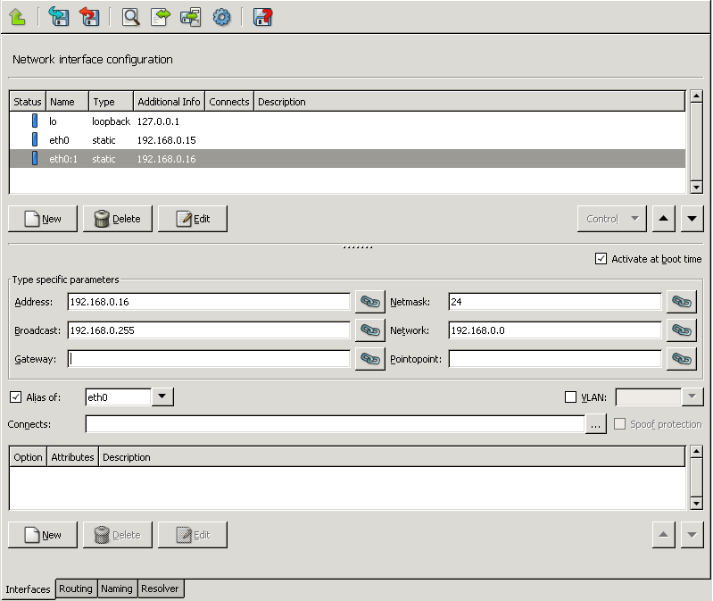
Using alias interfaces allows you to configure multiple IP addresses to a physical device. Alias interfaces are named in the following manner:
ethx:n where
- ethx
is the name of the corresponding physical or VLAN interface
- n
is the ID of the alias interface. The ID is usually a number (for example,
0for the first alias of the interface,1for the second, and so on), but it can be a more informative name too.
An alias can be defined for existing physical and VLAN interfaces.
5.1.2.2. Procedure – Creating an alias interface
Purpose:
To create an alias interface, complete the following steps.
Steps:
Every alias interface must be connected to a physical or a VLAN interface. If not already configured, configure this interface.
To create a new interface, click .
Set the of the interface. The type of the alias interface and the physical interface can be different.
-
Enter a name for the alias interface and click . The name must include the name of the physical or VLAN interface, the colon (
:) character, and the number or name that identifies the alias interface (because an interface can have several alias interfaces). For example,eth1:0.MC creates the new interface and automatically selects the alias option and the sets the parent interface of the alias.
Configure other options of the interface (for example, connected zones) as needed.
-
To activate the changes, click
and . Then select the parent interface of the alias, click , and the interface.Warning Restarting the interface might terminate all ongoing connections of the interface.
5.1.3. Procedure – Configuring bond interfaces
Purpose:
To create a bond interface, complete the following steps. The interfaces used to create the bond interface must be already configured. For details on configuring network interfaces, see Procedure 5.1.1.1, Configuring a new interface.
Steps:
Navigate to the host, and select the MC component.
To create a new interface, select . The dialog is displayed.
Enter a name for the interface (for example,
bond0) and set its type tostatic.Select .
Select
bond_slavesand enter the name of the interfaces to bond into the field. Use a single whitespace to separate the name of the interfaces (for example,eth0 eth1).Optional step: Select to set other bond-specific options as needed (for example,
bond_mode). If an option is not listed, type its name into the field and its value to the field.Configure the other parameters of the interface (for example, address, netmask, and so on) as needed.
To activate the changes, click
and .
5.1.4. Procedure – Configuring bridge interfaces
Purpose:
To create a bridge interface, complete the following steps. The interfaces used to create the bridge interface must be already configured. For details on configuring network interfaces, see Procedure 5.1.1.1, Configuring a new interface.
Steps:
Navigate to the host, and select the MC component.
To create a new interface, select . The dialog is displayed.
Enter a name for the interface (for example,
bridge0) and set its type tostatic.Select .
Select the
bridge_portsoption, and enter the name of the interfaces to bridge into the field. Use a single whitespace to separate the name of the interfaces (for example,eth0 eth1). To bridge every available interfaces, enterall.Optional step: Select to set other bridge-specific options as needed (for example,
bridge_stp). If an option is not listed, just type its name into the field and its value to the field. For a list of available options, see the bridge-utils-interfaces manual page.Configure the other parameters of the interface (for example, address, netmask, and so on) as needed.
To activate the changes, click
and .
Spoof protection means that the packet filter module of a firewall checks to ensure that packets arriving on an interface have source IP addresses that are legal in networks reachable through that given interface and accepts only those packages that match this criterion.
For example, if eth0 connects to the Intranet (10.0.0./8) and it is spoof-protected, the firewall does not accept datagrams on this interface with source IP addresses other than the 10.0.0.0/8 range. It does not accept datagrams with source IP address from the 10.0.0.0/8 range on interfaces other than eth0 either.
5.1.5.1. Procedure – Configuring spoof protection
Steps:
Select the interface and next to the field, click
.-
Select the zones the configured interface is connected to either directly or indirectly through routers.
Note The Zone tree in the dialog window is organized IP addresses, starting from the most generic (
0.0.0.0/0) to the most specific. There is an implicit inheritance in the specification: if the10.0.0.0/8address ranges is specified to connect toeth1, all more specific subnets of this address range (10.0.0.0/9,/10, .../32) connect toeth1also, unless a more specific binding is explicitly specified. -
Select .
Note The ruleset must be regenerated after modifying any interface settings. It is not done automatically.
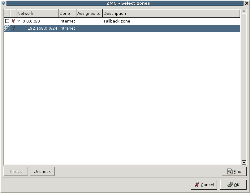
For further details on zones, see Section 6.2, Zones. For more information on Spoof control in relation with packet filter rules, see Section A.4.3.3, Spoof protection.
The bottom part of the tab can be used to specify activation scripts and various other parameters of the network interfaces. The following options can be configured:
Interface activation scripts can be useful for scenarios where special procedures are required to initialize networking.
For example, changing the Media Access Control (MAC) address of a network card before bringing it up can be done with a pre-up script. Such scripts should also be used for configuring bridge interfaces.
The following types of activation scripts can be set:
pre-up scripts are executed before the interface is activated.
up scripts activate the interface.
post-up scripts are executed after the interface is activated.
pre-down scripts are executed before the interface is deactivated.
down scripts deactivate the interface.
post-down scripts are executed after the interface is deactivated.
5.1.6.1.1. Procedure – Creating interface activation scripts
Purpose:
To create an interface activation script for an interface, complete the following steps.
Steps:
Navigate to and select the interface to configure.
-
To add a new option to the interface, click .
From the field, select the type of the script (
pre-up,up,post-up,pre-down,down,post-down).-
Enter the command to execute in the script into the field. Use full path name, for example,
/sbin/ifdown. To execute multiple commands, repeat Steps 2-4.
-
To set the order of commands, use the arrow buttons below the list of options.
Tip If you have to use complex scripts, create a script file on the PNS host using a text editor, and add an option to run it when needed.
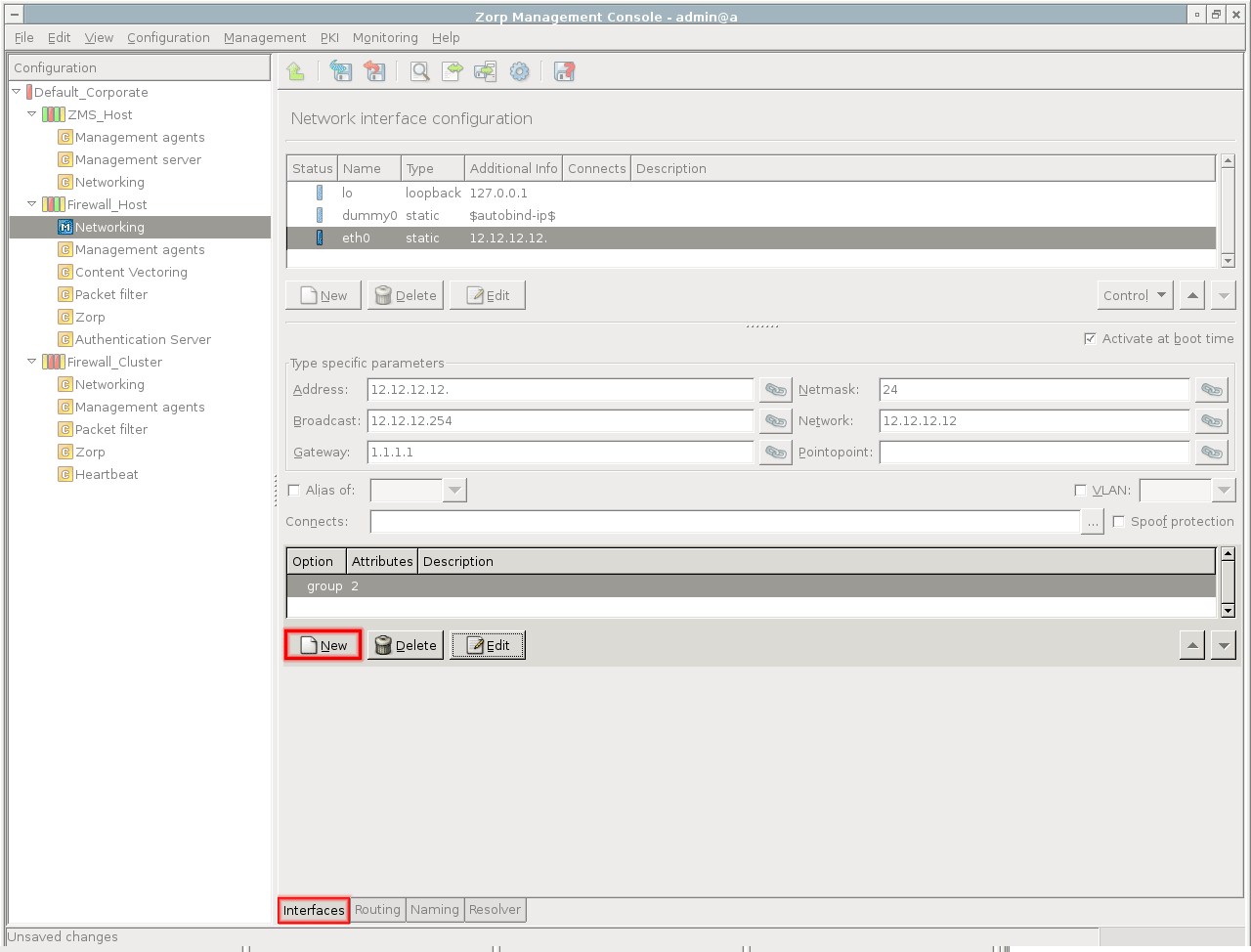
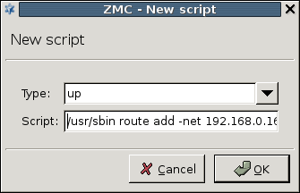
To simplify the management of services that are available from multiple zones and interfaces, interfaces can be grouped. Interfaces belonging to an interface group can be controlled together: the ifup and ifdown commands support interface groups too. Firewall rules can accept connections on interface groups too. For details on zones, services, and firewall rules, see Chapter 6, Managing network traffic with PNS.
5.1.6.2.1. Procedure – Creating interface groups
Purpose:
To assign interfaces to an interface group, complete the following steps.
Steps:
Navigate to the component and select the tab.
From the list of interfaces, select the interface to add to the group.
-
Under the list of options, click .
-
From , select
group.
Groups are identified by a number between
1–255. To assign the interface to a group, enter a number into the field.Click .
Repeat Steps 2–5 to add other interfaces to the group.
Commit and upload your changes. To activate the changes, restart the interface.
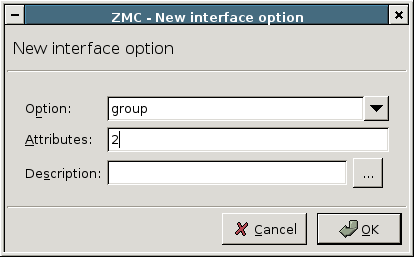
The following miscellaneous options can be configured for a network interface.
| Note |
|---|
It is rarely required to use these options in common scenarios. Only modify them if you know exactly what you are doing. |
: Sets the MAC address of the interface.
: Sets the metric used by the interface.
: Sets the Maximum Transfer Unit (MTU) of the interface.
: Sets the media type of the interface.
: Sets the Time to live (TTL) parameter of the interface.
5.1.6.3.1. Procedure – Configuring interface parameters
To configure an interface parameter, complete the following steps.
Navigate to the component and select the tab. Select the interface to configure.
To add a new option to the interface, click .
From the field, select the parameter that you want to configure.
Enter the value of the parameter into the field.
Commit and upload your changes. To activate the changes, restart the interface.
The state of the configured interfaces is indicated by leds of different colors before the name of the interface ( Green — Up, Red — Down, Blue — Unknown). The state of the interface is automatically updated periodically. The update frequency can be configured in . Status update can also be requested manually from the local menu of the interface. To do this, select the interface, right-click on it and select . Hovering the mouse over an interface displays a tooltip with status information and detailed statistics about the interface. The following status information is displayed:
: Status of the interface. Possible values:
Up,Down,Unknown.: Queuing discipline. For details, see the Traffic Control manual pages (man tc).
: Flags applicable to the interface. Possible values:
UP,BROADCAST,MULTICAST,PROMISC,NOARP,ALLMULTI,LOOPBACK.: Maximum Transmission Unit (MTU): the maximum size of a packet (in bytes) allowed to be sent from the interface.
The statistics about the traffic handled by the interface is divided into and sections, relevant for the received/sent packets, respectively.
: Number of errors encountered.
: Amount of data received.
: Number of packets received.
: Number of received multicast packets.
: Number of dropped packets.
: Number of overruns. Overruns usually occur when packets come in faster than the kernel can service the last interrupt.
: Number of collisions encountered.
: Amount of data sent.
: Number of packets sent.
: Number of errors encountered.
: Number of dropped packets.
: The number of carrier losses detected by the device driver. Carrier losses are usually the sign of physical errors on the network.

Variables on the tab directly correspond to the contents of /etc/hosts and /etc/networks files. Their use is mostly optional, name resolution is faster if most important name-IP address pairs are listed in /etc/hosts. A correctly configured resolver can provide the same service.
| Note |
|---|
If you intend to use the Postfix native proxy on the PNS host, you exceptionally have to supply the |
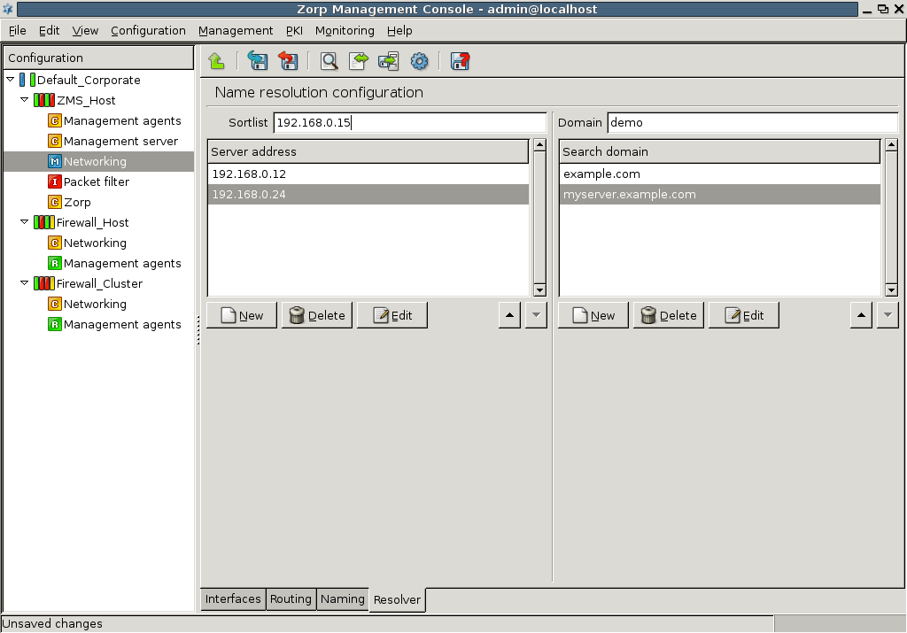
The client-side of DNS name resolution information can be configured on the tab.
| Note |
|---|
The Bind native proxy of PNS cannot be configured here. For information, see Chapter 9, Native services. |
In DNS terminology, the client initiating a name resolution query is called a resolver. For details about configuring a resolver correctly, refer to a good DNS documentation, see Appendix C, Further readings.
5.3.1. Procedure – Configure name resolution
List the nameservers to be used by your host in the right pane.
Set a priority order among the nameservers. The first one on the list is queried first.
-
Set up domain search order in the left pane.
Use the buttons with triangles on the right.
This information is used when you issue a name query for a hostname but without supplying the domain name parts: for example, telnet myserver. In this case the resolver automatically tries to append domain suffices to the hostname in the order you specify, before sending queries to nameservers.
In the example above, this would be
example.comand then if the query is unsuccessfulmyserver.example.com. -
OPTION
Define the preferred interface in the .
The sortlist directive specifies the preferred interface you wish to communicate on when, as a result of a query, you receive more than one IP address for a given host. The value of Sortlist can be a network IP address or a host IP address/subnet mask pair, where subnet mask is in the classic dotted decimal format and not in CIDR notation.
Tip The optimization using the Sortlist might be useful for firewalls with many interfaces installed or in the following special network setup.
The firewall is connected to the Internet with two interfaces: one for a broadband, primary connection and another, lower-bandwidth backup connection through a different ISP. If you want to reach a server on the Internet and the DNS query returns two IP addresses for the same server. From its routing table your firewall deduces that both IP addresses are reachable, but by default it uses the IP address that was listed first in the DNS response, even if that IP address is reachable through the — slower — backup line. To avoid this situation, you can explicitly tell your resolver with the Sortlist feature that whenever possible, it must prefer the interface that connects to the higher-bandwidth primary line.
Note that sortlist is just a preference and not an exclusive setting: if the targeted server cannot be reached via the interface designated by the sortlist parameter, the other interface(s) and IP addresses are tried.
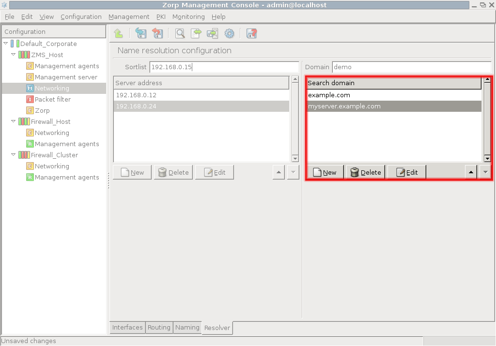
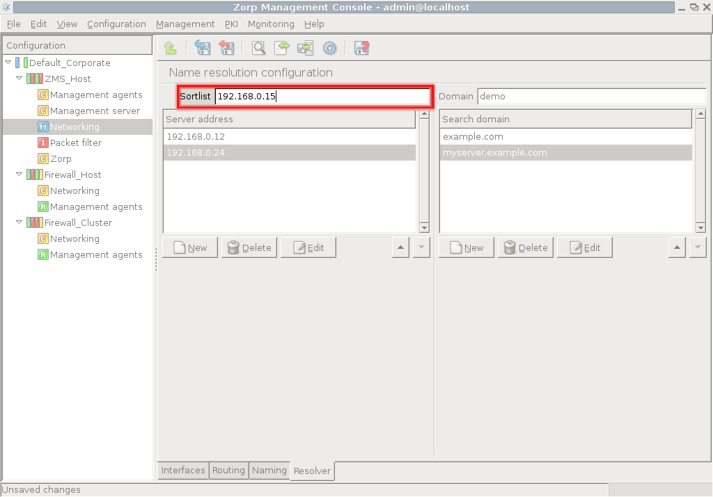
If a packet has to be delivered to a remote network, PNS consults the routing table to determine the path it should be sent. If there is no information in the routing table then the packet is sent to the default gateway. For maintaining and managing the routing table PNS offers a simple yet effective user interface on the tab of the MC component. It can be used to define static routes to specific hosts or networks through a selected interface.
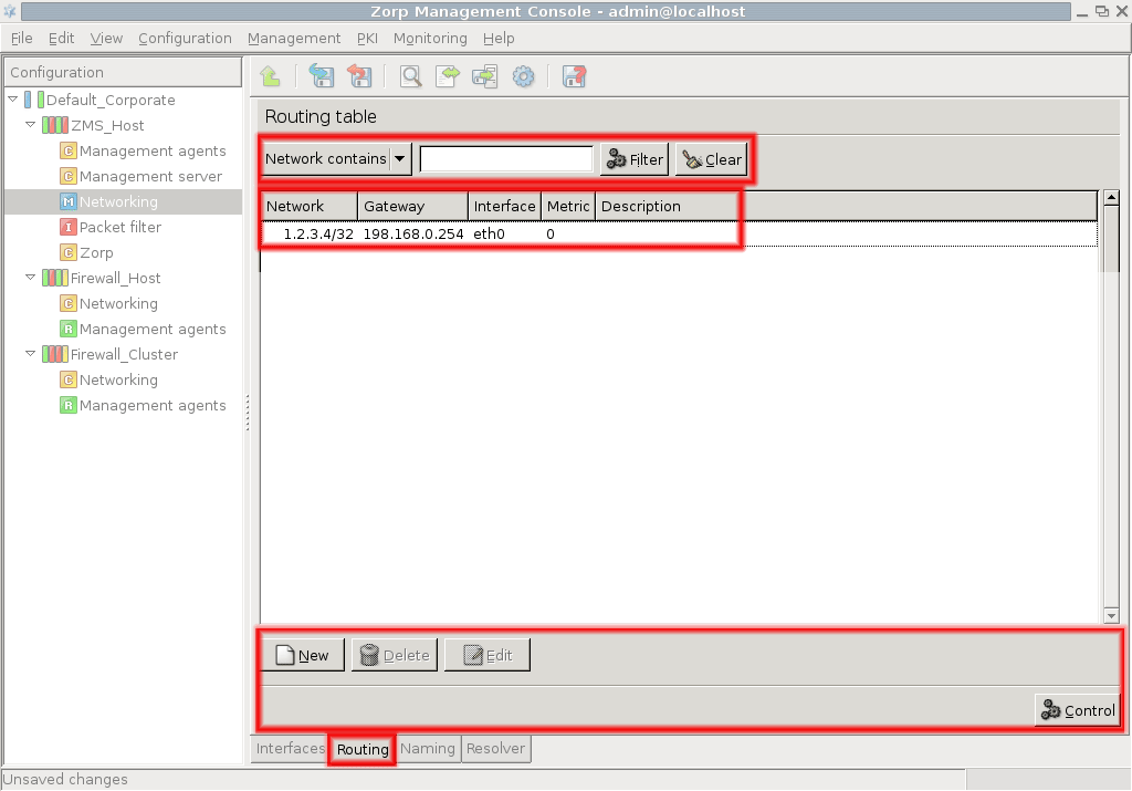
The tab contains the following elements:
A list of routing table entries in the middle of the panel.
A filter bar on the top for searching and filtering the entries.
A control bar on the bottom for managing the entries of the list and for activating the modifications of the routing table on the PNS firewall hosts.
A route has the following parameters:
: IP address of the network.
-
: Netmask of the network.
Note The IP address and netmask parameters are displayed in the column of the routing entries list.
: IP address of the gateway to be used for transmitting the packages.
: The Ethernet interface to be used for transmitting the packages. This parameter must be selected from the combobox listing the configured interfaces.
: An optional parameter to define a metric for the route. The metric is an integer from the
0 – 32766range.: Notes describing what this entry is used for.
The above parameters are interpreted the following way: messages sent to the Address/Netmask network should be delivered through Gateway using Interface.
New entries into the routing table can be added by clicking the button of the control bar; existing entries can be modified by clicking . The updated routing tables take effect only after the new configuration is uploaded to the host, and the routing tables are reloaded using the buttons of the control bar.
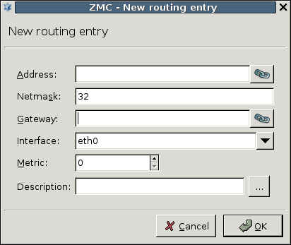
The list of routing table entries can be sorted by all of its parameters (network, gateway, and so on) by clicking on the header of respective column. By default, the list is displayed according to the general listing policy of the routing tables, that is, the networks connecting via a gateway are listed after the directly connected networks.
The list can be filtered using the filter bar above the list. Type the search pattern into the textbox, specify the elements to be searched using the combobox on the left, and click . The list will only display the routes matching the search criteria. Click to return to the full list.

Routes can be temporarily disabled by right-clicking the selected route and selecting from the appearing local menu.
| Note |
|---|
The route becomes disabled only after the routing table is reloaded. |
When the PNS host is administered via a terminal, the routes have to be entered manually by editing the /etc/network/static-routes configuration file. Each line of this file corresponds to a route, and has the following format:
interface_name to address/netmask through gateway metric [metric]
For the modifications to take effect, the routing tables have to be reloaded by issuing the /usr/lib/zms-transfer-agent/zms-routing params="reload" command.
This chapter describes how to allow traffic to pass the PNS firewall. It gives detailed explanation of the many features and parameters of PNS.
This section provides an overview of how Application-level Gateway handles incoming connections, and the task and purpose of the different PNS components.
Application-level Gateway firewall rules permit and examine connections between the source and the destination of the connection. When a client tries to connect a server, Application-level Gateway receives the connection request and finds a firewall rule that matches the parameters of the connection request based on the client's address, the target port, the server's address, and other parameters of the connection. The rule selects a service to handle the connection. The service determines what happens with the connection, including the following:
The Transport-layer protocol permitted in the traffic. For example, TCP or UDP.
The service started by the firewall rule. This also determines the application-level protocol permitted in the traffic. Application-level Gateway uses proxy classes to verify the type of traffic in the connection, and to ensure that the traffic conforms to the requirements of the protocol, for example, downloading a web page must conform to the HTTP standards.
The address of the destination server. Application-level Gateway determines the IP address of the destination server using a router. Routers can also modify the target address if needed.
The content of the traffic. Application-level Gateway can modify protocol elements, and perform content vectoring. See Chapter 14, Virus and content filtering using CF for details.
How to connect to the server. For nontransparent connections, Application-level Gateway can connect to a backup server if the original is unreachable, or perform loadbalancing between server clusters.
Who can access the service. Application-level Gateway can authenticate and authorize the client to verify the client's identity and privileges. See Chapter 15, Connection authentication and authorization for details.
The operations and policies configured in the service definition are performed by a Application-level Gateway instance.
Zones describe and map the networking environment on the IP level. IP addresses are grouped into zones; the access policies of PNS operate on these zones. Zones specify segments of the network from which traffic can be received (source) or sent to (destination) through the firewall. Zones in PNS can contain:
IP networks,
subnets,
individual IP addresses, and
hostnames.
The actual implementation of a zone hierarchy depends on the network environment, and the placement and role of PNS firewalls, the security policy, and so on.
The Internet zone which covers all possible IP addresses is defined on every site by default. If an IP address is not included in any user-defined zones, it belongs to the Internet zone. PNS policies permit traffic between two or more zones, so at least another zone — the intranet — must be created. Usually a special zone called demilitarized zone (DMZ) is defined for servers available from the Internet.
Zones in PNS can have a hierarchy, with a zone containing many subzones that may have their own subzones, and so on. From these zones, a tree hierarchy can be constructed. This hierarchy is purely administrative and independent from the IP addresses defined in the zones themselves: for example, a zone that contains the 192.168.7.0/24 subnet can have a subzone with IP addresses from the 10.0.0.0/8 range.
A network can belong only to a single zone, because otherwise the position of IP addresses in the network would be ambiguous.
The zone hierarchy is independent from the subnetting practices of the company or the physical layout of the network, and can follow arbitrary logic. The zone hierarchy applies to every host of a site.
| Note |
|---|
Subnets can be used directly in PNS configurations, it is not necessary to include them in a zone. |
| Note |
|---|
It is recommended to follow the logic of the network implementation when defining zones, because this approach leads to the most flexible firewall administration. Plan and document the zone hierarchy thoroughly and keep it up-to-date. An effective and usable zone topology is essential for successful PNS administration. |
By default, MC defines a zone called internet on every site. The internetcontains the the 0.0.0.0 and the ::0 networks with the 0 subnet mask. This zone means any network: every IP address not belonging to another zone belongs to the internet zone.
| Note |
|---|
PNS uses the CIDR notation for subnetting. |
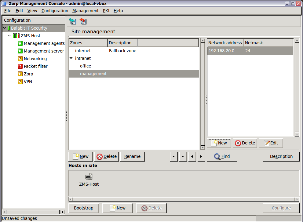
The internet zone is typically used in firewall rules where one side of the connection cannot be defined more exactly.
| Example 6.1. Using the Internet zone |
|---|
The Internet zone identifies all external networks. To allow the internal users to visit all web pages, simply set the destination zone of the HTTP service to |
Zones are managed on the component in MC. The left side of the main workspace displays the zones defined on the site and their descriptions. IP networks that belong to the selected zone are displayed on the right side of the workspace.
| Note |
|---|
The MC component has a shortcut in its icon bar to the zone editor. The zone hierarchy applies to all firewalls of the site, so carefully consider every modification and its possible side-effect. |
Use the control buttons to create, delete, or edit the zone definitions and the IP networks. Use the arrow icons to organize the zones into a hierarchy (see Section 6.2.3, Zone hierarchies for details).
6.2.2. Procedure – Creating new zones
To create a new zone on the site, complete the following steps.
-
Select the site from the configuration tree and click .
-
Enter a name for the zone in the displayed window.
Tip Use descriptive names and a consistent naming convention. Zone names may refer to the physical location of the network or the department using the zone (for example,
building_B, ormarketing). -
To add an IP network to the zone, click in the Networks pane.
-
To add a network or an IP address to the zone, select , fill the and fields, then click .
To add a hostname to the zone, select , enter the hostname into the field, then click . For details on using hostnames in zones, see Section 6.2.4, Using hostnames in zones.
Repeat this step to add other networks to the zone.
Note The new zone has effect only if used in a firewall rule definition.
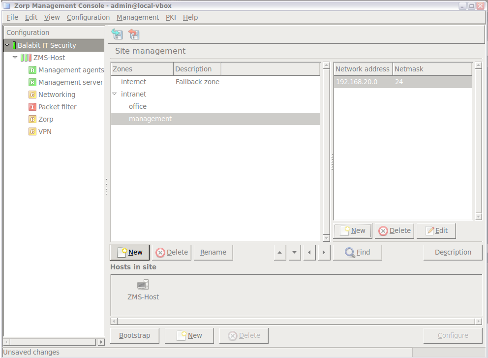
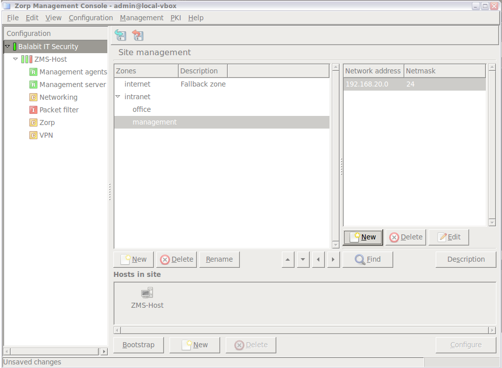
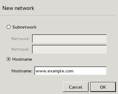
Zones can be organized into a tree, much like the directories of a file system. Define a topmost zone and with many subzones, each for administratively different parts of your networks. A zone and its subzone have parent-child relationship: child zones automatically inherit all properties and settings of their parents. For example, Zone A is the parent zone of Zone B, and all clients in Zone A may browse the web through HTTP. Zone B inherits this setting, so all clients of Zone B have unrestricted HTTP access.
To stop a zone from inheriting the properties of the parent zone, use a DenyService. For details on DenyServices, see Procedure 6.4.3, Creating a new DenyService.
Zones can be reorganized as needed.
| Note |
|---|
Changing parent-child relations also changes the inheritance chain — which might cause unexpected results on your firewall policies. Make sure to keep up-to-date documentation of your firewall configuration. |
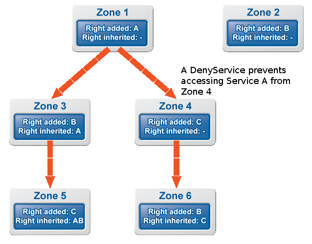
6.2.3.1. Procedure – Organizing zones into a hierarchy
To organize zones into a hierarchy, complete the following steps.
Select the site from the configuration tree in MC.
-
Using the up and down arrows located next to the button, move the child zone below its parent.
Click the right arrow to make the selected zone a children of the zone above it.
-
Commit the changes to the site.
Note Zone definitions are site-wide, so modifications are effective on every firewall of the site.
-
Select all hosts of the site and upload the configuration.
This step is required because changes in the zone hierarchy must be uploaded to all firewall nodes.
Select all hosts of the site, click the icon of the icon bar and reload the configuration.
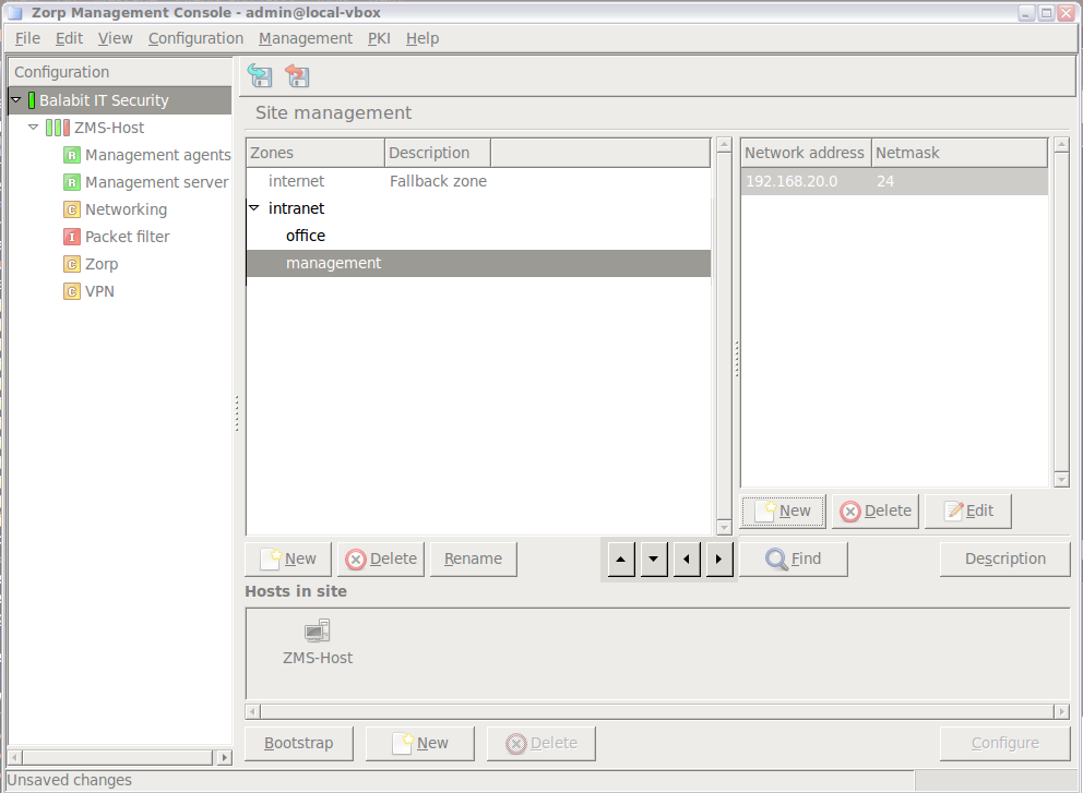
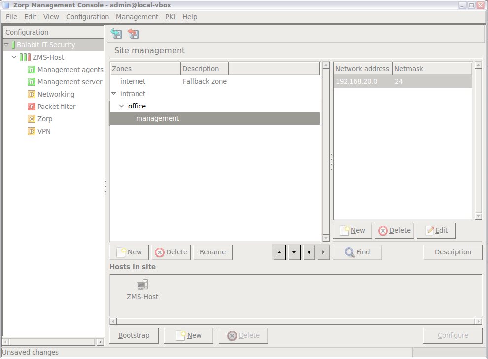
To remove a child zone from the hierarchy, select the zone and click the left arrow.
Starting with PNS 5.0, you can directly use hostnames in zones. During startup, PNS automatically resolves these hostnames to /32 IP addresses, and updates them periodically to follow any changes in the IP addresses related to the hostname. When using hostnames in zones, note the following points and warnings:
Ensure that your Domain Name Server (DNS) is reliable and continuously available. If you cannot depend on your DNS to resolve the hostnames, do not use hostnames in zones.
Do not use zones that include hostnames to deny access, that is, do not use such zones in DenyServices. If PNS cannot resolve a hostname, it will omit the hostname from the zone. If the zone contains only a single hostname (because you want to use it to restrict access to a specific site), the zone will be empty, that will never match any connection. If you have a firewall rule that is more permissive than the DenyService you are using the zone with the hosname, this more permissive rule will be effective, permitting traffic you want to block. (For example, you create a rule that permits HTTP traffic to the Internet, and a DenyService to block HTTP traffic to the example.com hostname. If PNS cannot resolve the example.com hostname, then the broader, more permissive rule will permit traffic to the example.com site.)
If the hostname is resolved to an IP address that is explicitly used in another zone, then PNS will use the rule with the explicit IP address. For example, you have a zone that includes the example.com hostname, another zone that includes the
192.168.100.1/32IP address, and you have two different rules that use these zones (Rule_1 uses the hostname, Rule_2 the explicit IP address). If the example.com hostname is resolved to the 192.168.100.1 IP address, PNS will use Rule_2 instead of Rule_1.If more than one hostname is resolved to the same IP address, PNS ignores each hostname and logs an error message. For example, this means that you cannot use a hostname in a zone if the server uses name-based virtual hosting.
Zones are global in PNS, and apply to all firewalls of the site, so carefully consider every modification of a zone, and its possible side-effect.
To find a zone or a subnet, select the site in the configuration tree and click the button.
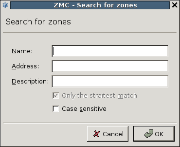
You can search for the name of the zone, or for the IP network it contains. When searching for IP networks, the only the most specific zone containing the searched IP is returned. If an IP address belongs to two different zones, the straitest match returns the most specific zone.
| Tip |
|---|
The tool is especially useful in large-scale deployments with complex zone and subnet structure. |
Instances of Application-level Gateway are groups of services that can be controlled together. A PNS firewall can run multiple instances of the Application-level Gateway process. The main benefits of multiple firewall instances are the following:
-
Administration
A typical firewall handles many types of traffic, many different protocols. These protocols might have different administrative requirements. Inbound traffic is usually handled differently from outbound traffic. For these reasons, using multiple firewall instances can make administration more transparent.
-
Availability
If an error (for example, misconfiguration) occurs and the firewall instance stops responding, no traffic can pass the firewall. However, an error usually affects a single instance; the other ones are still functional, so only the traffic handled by the crashed instance stops. Instances can be controlled (started, restarted, stopped) individually from each other. This is important, because stopping or restarting an instance stops all traffic handled by the instance.
Consider the following example. A firewall uses two instances:
Instance_Afor all e-mail related traffic (the POP3, IMAP, and the SMTP protocols) andInstance_Bfor everything else (HTTP, and so on). IfInstance_Astops because of an error, or is stopped by the administrator, no e-mails can be sent or received. However, all other network traffic is working. -
Performance
Separate firewall instances have separate processes and separate sets of threads, significantly increasing the performance on multiprocessor systems (SMP or HyperThreading).
-
Logging
Log settings are effective on the instance level; different instances can log in differently. For example, if higher than average logging level is required for a type of traffic, it might worth to create an instance for this traffic and customize logging only for this instance.
| Note |
|---|
|
Although creating instances is beneficial, the number of instances that can run on a system is limited. Each instance is a separate process and requires its own space in the system memory — quickly consuming the limited physical resources of the computer. More instances do not necessarily make configuration tasks easier, and complex configuration increases the chance of human errors. Keep instance number relatively low unless you have a solid reason to use many instances. |
Instances usually handle traffic based on the protocol used by the traffic, the direction of the traffic, or a special characteristic of the traffic (for example, requires authentication). It is common practice to define an instance for all inbound traffic that handles all services accessible from the Internet, and another one for all traffic that the clients of intranet are allowed to use. Consider creating a separate instance for:
special services, for example, mission-critical traffic;
traffic accessing critical locations, for example, your servers;
traffic that requires outband authentication.
To manage Application-level Gateway instances, navigate to the tab of the MC component.
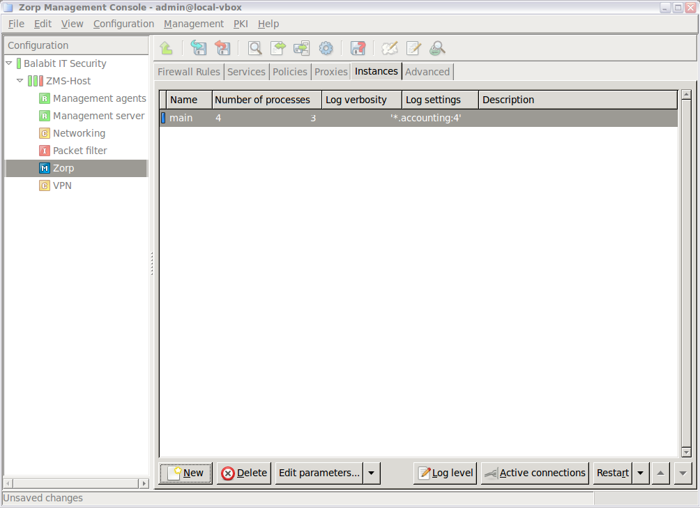
The following information is displayed for each instance:
-
: Name and state of the instance. The colored led shows the state of the instance:
Green – Running
Red – Stopped
Blue – Unknown. New instances that were not started yet are in this state.
: The number of CPU cores that the instance can maximally use. Select to modify this setting. Default value: 1
: The log level set for the instance.
: The log specifications of the instance.
: A description of the instance, for example, the type of traffic it handles.
Hovering the mouse over an instance displays a tooltip with detailed information, including the number of processes running in the instance, as well as the number of running threads for each process.
Use the button bar below the instances table to manage and configure the instances.
: Create a new instance. On a freshly installed PNS, there are no instances — you have to create one first. See Procedure 6.3.3, Creating a new instance for details.
-
: Remove an instance.
Warning Deleting an instance makes the services handled by the instance unaccessible.
: Modify the name or parameters of the instance. See Section 6.3.5, Instance parameters — general for details. To modify the parameters of every instance, select
 > Default parameters.
-
: Restart the instance. To Reload, Restart, Stop, or Start an instance, click Restart
and select the desired action. These functions are needed after modifying the configuration of an instance. sets the verbosity of logging. displays the connections currently handled by the instance (see Section 6.8, Monitoring active connections for details).Tip Use the Shift or the Control key to select and control multiple instances.
: Move the instance up or down in the list. When PNS boots, the instances are started in the order they are listed.
6.3.3. Procedure – Creating a new instance
To create a new instance on a PNS firewall host, complete the following steps:
-
Navigate to the tab of the MC component on the PNS host.
Note If the and the components are not available on the selected host, you have to add them first. See Procedure 3.2.1.3.1, Adding new configuration components to host for details.
-
Click the button located below the table.
-
Enter a name for the new instance.
Note Use informative names containing information about the direction and type of the traffic handled by the instance, for example,
intra_httporintra_pop3referring to instances that handle HTTP and POP3 traffic coming from the intranet. Use direction names consistently, for example, include the source zone of the traffic. Describe the purpose of the instance in the field.
To modify the parameters of the instance, uncheck the option and adjust the parameters as needed. For details on the available parameters, see Section 6.3.5, Instance parameters — general.
Click .
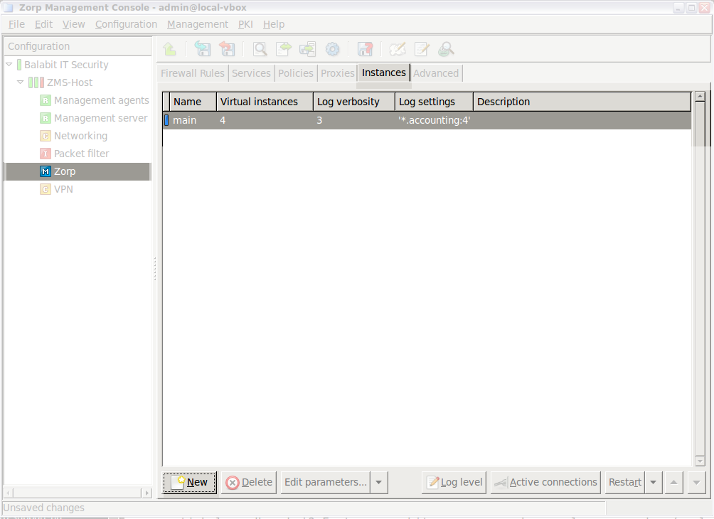
6.3.4. Procedure – Configuring instances
To modify the parameters of an instance, complete the following steps.
Navigate to the tab of the MC component on the PNS host.
-
To modify the configuration of every instance on the site, select
> Default parameters.To modify the configuration of a single instance, select an instance and click . The window is displayed. Uncheck the option.
Adjust the settings as needed, then click . Instance parameters are grouped into four tabs. See Section 6.3.5, Instance parameters — general for details on the available parameters.
Commit and upload the changes.
To activate the changes, select button to or Restart
> Reload.
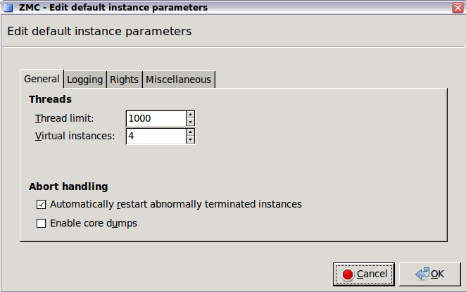
To modify instance parameters, select . The tab has the following parameters:
: Uncheck this option to inactivate the instance.
: The name of the instance.
: When renaming and instance and this option is enabled, Application-level Gateway stops the instance, renames it, then starts the renamed instance.
: The description of the instance.
: The number of threads the instance can start. Set according to the anticipated number of concurrent connections. Most of the active client requests requires its own thread. If the is too low, the clients will experience delays and refused connection attempts.
-
: The number of Application-level Gateway processes the instance can start. This setting determines the number of CPU cores that the instance can use. If our PNS host has many CPUs, increase this value for instances that have high traffic. Note that the
Thread limitandThread stack limitparameters are apply separately for every process. For details on increasing the number of running processes, see Procedure 6.3.9, Increasing the number of running processes.For every process, Application-level Gateway uses a certain amount of memory from the stack. At most, a process uses the default value of the stack size of the host (which is currently 8 MB for Ubuntu 18.04 LTS). Application-level Gateway uses this memory only when it is actually needed by the thread, it is not allocated in advance.
: If enabled, Application-level Gateway automatically restarts instances that crash for some reason.
: If enabled, PNS automatically creates core dumps when a Application-level Gateway instance crashes for some reason. Core dumps are special log files and are needed for troubleshooting.
Instance parameters can be set on the tabs of the window. The tab has the following parameters:
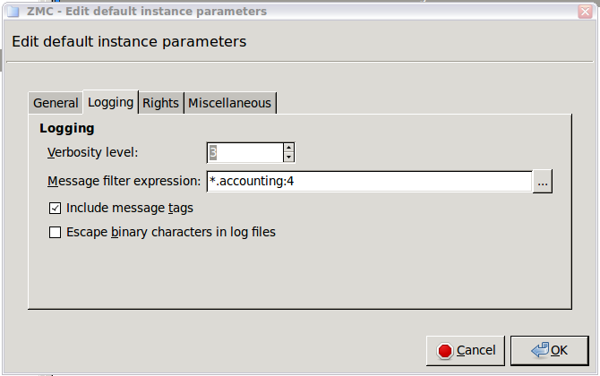
-
: The general verbosity of the instance. Ranges from 0 to 9; higher value means more detailed logging.
Note Setting a high verbosity level (above 6) can dramatically decrease the performance. On level 9 Application-level Gateway logs the entire passing traffic.
Tip The default verbosity level is 3, which logs every connection, error and violation without many details.
Level 4 to 6 include protocol-specific information as well.
Levels 7 to 9 are recommended only for troubleshooting and debugging purposes.
: Sets the verbosity level on a per-category basis. Each log message has an assigned multi-level category, where levels are separated by a dot. For example, HTTP requests are logged under
http.request. A log specification consists of a wildcard matching log category, a colon, and a number specifying the verbosity level of that given category. Separate log specifications with a comma. Categories match from left to right. For example,http.*:5,core:3. The last matching entry will be used as the verbosity of the given category. If no match is found the default verbosity is used.: Prepend log category and log level to each message.
: Replace non-printable characters with
XXto avoid binary log files. Characters with codes lower than0x20or higher than0x7F.
| Note |
|---|
Customized logging can be very useful, but should be used with caution. Too many log specifications can decrease the overall performance of Application-level Gateway. |
Instance parameters can be set on the tabs of the window. The tab has the following parameters:
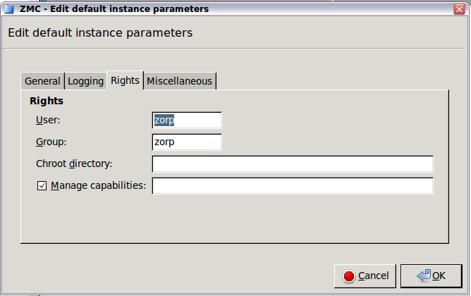
| Warning |
|---|
Modify these settings only if you know what you are doing, because bad rights configuration can prevent Application-level Gateway from starting. |
: Run Application-level Gateway as this user. By default, Application-level Gateway runs as the normal user
zorp.: Run Application-level Gateway as a member of this group.
: Change root to this directory before reading the configuration file.
:
Instance parameters can be set on the tabs of the window. The tab has the following parameters:
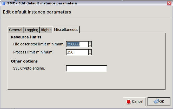
:
:
: The OpenSSL crypto engine to be used for hardware accelerated crypto support.
6.3.9. Procedure – Increasing the number of running processes
To increase the number of running processes in a Application-level Gateway instance, complete the following steps.
Steps:
Navigate to the tab of the MC component on the PNS host.
Select the instance you want to modify, and click .
Uncheck the option.
On the tab, adjust the option, and click .
Commit and upload your changes.
the instance.
the instance.
Services define the traffic that can pass through the firewall. A service is not a software component, but a group of parameters that describe what kind of traffic should Application-level Gateway accept and how to handle the accepted traffic. The service specifies how thoroughly the traffic is analyzed (packet filter or application level), the protocol of the traffic (for example, HTTP, FTP, and so on), if the traffic is TLS-encrypted (and also related security settings like accepted certificates) NAT policies applied to the connections, and many other parameters.
Packet-filter services forward the incoming packets using the kzorp kernel module. Application-level services create two separate connections on the two sides of Application-level Gateway (client–Application-level Gateway, Application-level Gateway–server) different connections and analyze the traffic on the protocol level. Only application-level services can perform content filtering, authentication, and other advanced features.
| Note |
|---|
To allow IPSec traffic to pass PNS, you must add packet-filtering rules manually. See Procedure 16.3.3, Forwarding IPSec traffic on the packet level for details. |
The following types of services are available in Application-level Gateway:
: Inspects the traffic on the application level using proxies. For the highest available security, use application-level inspection whenever possible. For details, see Procedure 6.4.1, Creating a new service
: Inspects the traffic only on the packet level. Use packet-level filtering to transfer very large amount of UDP traffic (for example, streaming audio or video). For details, see Procedure 6.4.2, Creating a new PFService.
: To make a service unavailable for some reason (for example, because accessing it is prohibited in certain zones), use . DenyService is a replacement for the umbrella zones of earlier Application-level Gateway versions. For details, see Procedure 6.4.3, Creating a new DenyService.
: Attempts to determine the protocol used in the connection from the traffic itself, and start a service specified. Currently it can detect HTTP, SSH, and SSL traffic. For HTTPS connections, it can also select a service based on the certificate of the server. For details, see Procedure 6.4.4, Creating a new DetectorService.
Services are managed from the tab of the MC component. The left side of the tab displays the configured services, while the right side shows the parameters of the selected service. Use this tab to delete unwanted services, modify existing ones, or create new ones.
6.4.1. Procedure – Creating a new service
To create a new service that inspects a traffic on the application level, complete the following steps.
-
Navigate to the Services tab of the Application-level Gateway MC component and click .
-
Enter a name for the service into the opening dialog. Use clear, informative, and consistent service names. You are recommended to include the following information in the service name:
Source zones, indicating which clients may use the service (for example,
intranet).The protocol permitted in the traffic (for example,
HTTP).Destination zones, indicating which servers may be accessed using the service (for example,
Internet).
Tip Name the service that allows internal users to browse the Web
intra_HTTP_internet. Use dots to indicate child zones, for example,intra.marketing_HTTP_inter. Click
in the field and select Service.-
In the field, select the application-level proxy that will inspect the traffic. Only traffic corresponding to the selected protocol and the settings of the proxy class can pass the firewall.
Note Application-level Gateway has many proxy classes available by default. These can be used as-is, or can be customized if needed.
For details on customizing proxy classes, see Section 6.6, Proxy classes.
The settings and parameters of the proxy classes are detailed in the Chapter 4, Proxies in Proxedo Network Security Suite 1.0 Reference Guide.
To permit any type of Layer 7 traffic, select . The PlugProxy is a protocol-independent proxy.
Optional Step: If the inspected traffic will be SSL or TLS-encrypted, select the Encryption Policy to use in the field. For details, see Section 6.7.3, Encryption policies.
Optional Step: In the section, select the method used to determine the IP address of the destination server. For details, see Section 6.4.5, Routing — selecting routers and chainers.
-
Optional Step: In the section, the Network Address Translation policy used to NAT the address of the client (SNAT), the server (DNAT), or both. For details, see Section 6.7.5, NAT policies.
Note To remove a policy from the service, select the empty line from the combobox.
Note NAT policies cannot be used in PFServices for IPv6 traffic.
Optional Step: In the field, select the method used to connect to the destination server. See Section 6.4.5, Routing — selecting routers and chainers for details.
-
Optional Step: To specify exactly which zones can be accessed using the service, click and select the permitted zones. If this option is set, the target server must be located in the selected zones, otherwise Application-level Gateway will reject the connection.
Note The zone set in the option is the actual location of the target server. This is independent from the destination address of the client-side connection.
This option replaces the functionality of the
inband_servicesparameter of the zone. Optional Step: In the section, select the authentication and authorization policies used to verify the identity of the client. See Chapter 15, Connection authentication and authorization for details.
Optional Step: In the field, select how Application-level Gateway should resolve the addresses of the client requests. See Section 6.7.6, Resolver policies for details.
Optional Step: To limit how many clients can access the service at the same time, set the option. By default, Application-level Gateway does not limit the number of concurrent connections for a service (0).
Optional Step: To send keep-alive messages to the server, the client, or both, to keep the connection open even if there is no traffic, set the option to
Z_KEEPALIVE_SERVER,Z_KEEPALIVE_CLIENT, orZ_KEEPALIVE_BOTH.Commit your changes.
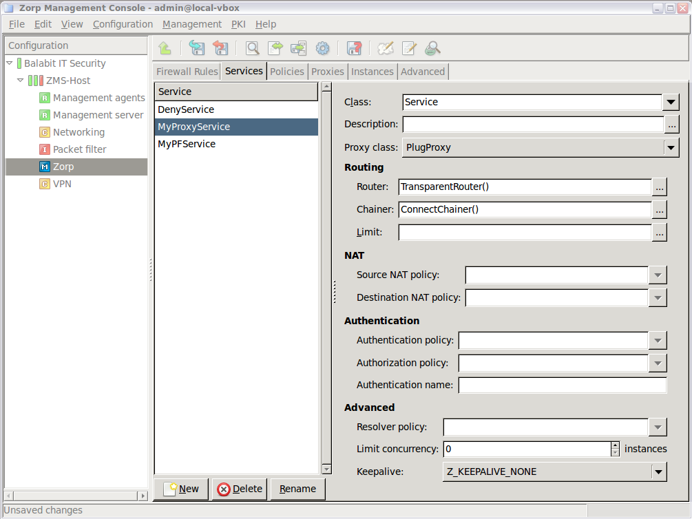
6.4.2. Procedure – Creating a new PFService
To create a new packet-filter service that inspects a traffic on the packet level, complete the following steps.
-
Navigate to the Services tab of the Application-level Gateway MC component and click .
-
Enter a name for the service into the opening dialog. Use clear, informative, and consistent service names. You are recommended to include the following information in the service name:
Source zones, indicating which clients may use the service (for example,
intranet).The protocol permitted in the traffic (for example,
HTTP).Destination zones, indicating which servers may be accessed using the service (for example,
Internet).
Tip Name the service that allows internal users to browse the Web
intra_HTTP_internet. Use dots to indicate child zones, for example,intra.marketing_HTTP_inter. Click
in the field and select PFService.-
To spoof the IP address of the client in the server-side connection (so that the target server sees as if the connection originated from the client), select the option.
Note For IPv6 traffic, the PFService will always spoof the client address, regardless of the setting of the option.
To redirect the connection to a fixed address, select , and enter the IP address and the port number of the target server into the respective fields. You can use links as well.
-
Optional Step: In the section, the Network Address Translation policy used to NAT the address of the client (SNAT), the server (DNAT), or both. For details, see Section 6.7.5, NAT policies.
Note To remove a policy from the service, select the empty line from the combobox.
Note NAT policies cannot be used in PFServices for IPv6 traffic.
Commit your changes.
6.4.3. Procedure – Creating a new DenyService
To create a new DenyService that prohibits access to certain services, complete the following steps.
-
Navigate to the Services tab of the Application-level Gateway MC component and click .
-
Enter a name for the service into the opening dialog. Use clear, informative, and consistent service names. You are recommended to include the following information in the service name:
Source zones, indicating which clients may use the service (for example,
intranet).The protocol permitted in the traffic (for example,
HTTP).Destination zones, indicating which servers may be accessed using the service (for example,
Internet).
Tip Name the service that allows internal users to browse the Web
intra_HTTP_internet. Use dots to indicate child zones, for example,intra.marketing_HTTP_inter. Click
in the field and select DenyService.-
To specify how Application-level Gateway rejects the traffic matching a DenyService, use the and options. By default, Application-level Gateway simply drops the traffic without notifying the client.
Commit your changes.
6.4.4. Procedure – Creating a new DetectorService
To create a new DetectorService that starts a service based on the traffic in the incoming connection, complete the following steps.
-
Navigate to the Services tab of the Application-level Gateway MC component and click .
-
Enter a name for the service into the opening dialog. Use clear, informative, and consistent service names. You are recommended to include the following information in the service name:
Source zones, indicating which clients may use the service (for example,
intranet).The protocol permitted in the traffic (for example,
HTTP).Destination zones, indicating which servers may be accessed using the service (for example,
Internet).
Tip Name the service that allows internal users to browse the Web
intra_HTTP_internet. Use dots to indicate child zones, for example,intra.marketing_HTTP_inter. In the section, select the TransparentRouter option.
Click
in the field and select DetectorService.-
Commit your changes.
Navigate to , and create a firewall rule that uses the DetectorService you created in the previous steps.
-
Click , select a DetectorPolicy, and select a service that Application-level Gateway will start if the traffic matches the DetectorPolicy. If you add more DetectorPolicy-Service pairs, Application-level Gateway will evaluate them in order, and start the service set for the first matching DetectorPolicy. If none of the DetectorPolicies match the traffic, Application-level Gateway terminates the connection.
Note When using a DetectorService, establishing the connection is slower, because Application-level Gateway needs to evaluate the content of the traffic before starting the appropriate service. If the rate of incoming connection requests that use the DetectorService is high, the clients may experience performance problems during connection startup. Note that using a DetectorService has no effect on the performance after the connection has been established.
Routers define the target IP address and port for the traffic. The default router, called TransparentRouter, uses the IP address requested by the client. The destination selected by a router may be later overridden by the proxy (if the Target address overridable by the proxy option of the router is enabled) and the chainer.
Routers suggest the destination IP; chainers establish the connection with the selected destination. The default ConnectChainer simply connects the destination selected by the router.
6.4.5.1. Procedure – Setting routers and chainers for a service
To set a router or a chainer for a service, complete the following steps.
Navigate to the tab of the MC component and select the service to modify.
-
Click to select and configure a router. By default, the TransparentRouter is selected. The following routers are available:
-
Click to select and configure a chainer. By default, the ConnectChainer is selected. The following chainers are available:
Commit your changes.
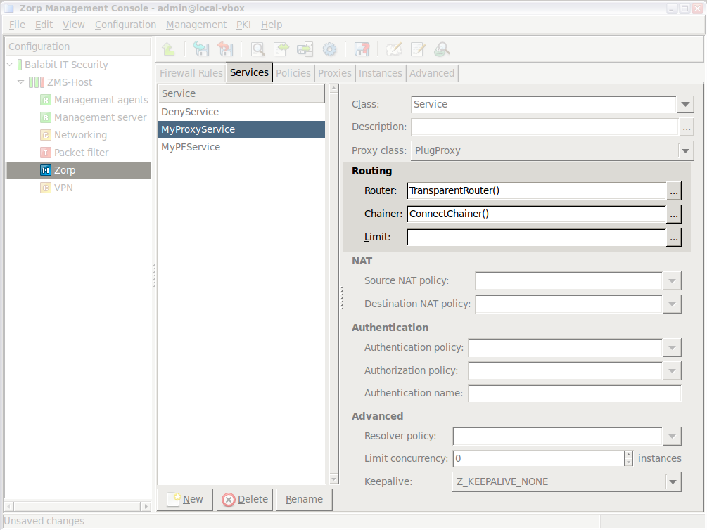
TransparentRouter does not modify the IP address and TCP/UDP port number requested by the client; the same parameters are used on the server side.
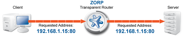
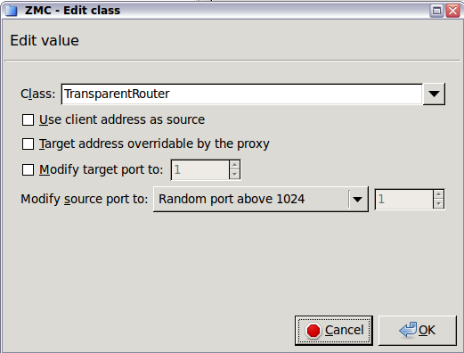
By default, Application-level Gateway uses its own IP address in the server-side connections: the server does not see the IP address of the original client. By selecting this option, Application-level Gateway mimics the original address of the client. Use this option if the server uses IP-based authentication, or the address of the client must appear in the server logs.
| Note |
|---|
This option was called Forge address in earlier versions of PNS. |
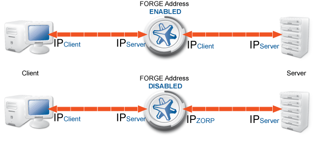
| Note |
|---|
The IP address of the client is related to the source NAT (SNAT) policy used for the service: using SNAT automatically enables the Use client address as source option in the router. |
If this option is selected and the data stream in the connection contains routing information, than the address specified in the data stream is used as the destination address of the server-side connection.
| Note |
|---|
|
The Target address overridable by the proxy option cannot be used with InbandRouter. This option was called Overridable in earlier versions of PNS. |
Use the option to connect to a different port of the server.
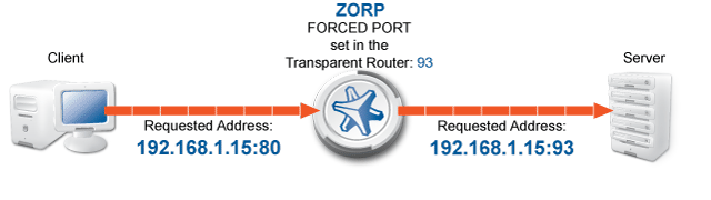
This option defines the source port that Application-level Gateway uses in the server-side connection. The following options are available:
Random port above 1024: Selected a random port between 1024 and 65535. This is the default behavior of every router.
Random port in the same group: Select a random port in the same group as the port used by the client. The following groups are defined: 0-513, 514-1024, 1025–.
Client port: Use the same port as the client.
Specified port: Use the port set in the spinbutton.
| Note |
|---|
This option was called Forge port in earlier versions of PNS. |
DirectedRouter directs all connections to fixed addresses, regardless of the address requested by the client.
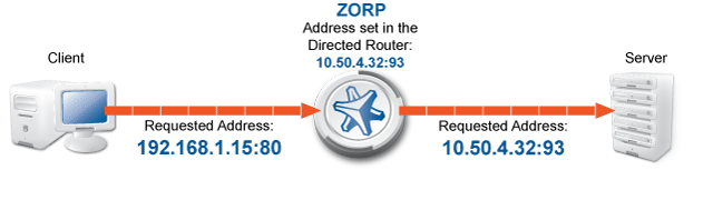
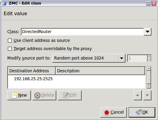
To add a destination address, click , and enter the IP address and port number of the server to connect to. If you set additional addresses, and the first address is unreachable, Application-level Gateway tries to connect the next server. It is also possible to connect to the listed destinations in a round-robin fashion, see Section 6.4.5.7, RoundRobinChainer for details.
| Tip |
|---|
Use DirectedRouter for servers publicly available in the DMZ. That way outsiders do not know the real IP addresses of the servers — the servers are not even required to have public, routable IP addresses. |
DirectedRouter has the following options.
By default, Application-level Gateway uses its own IP address in the server-side connections: the server does not see the IP address of the original client. By selecting this option, Application-level Gateway mimics the original address of the client. Use this option if the server uses IP-based authentication, or the address of the client must appear in the server logs.
| Note |
|---|
This option was called Forge address in earlier versions of PNS. |
| Note |
|---|
The IP address of the client is related to the source NAT (SNAT) policy used for the service: using SNAT automatically enables the Use client address as source option in the router. |
If this option is selected and the data stream in the connection contains routing information, than the address specified in the data stream is used as the destination address of the server-side connection.
| Note |
|---|
|
The Target address overridable by the proxy option cannot be used with InbandRouter. This option was called Overridable in earlier versions of PNS. |
This option defines the source port that Application-level Gateway uses in the server-side connection. The following options are available:
Random port above 1024: Selected a random port between 1024 and 65535. This is the default behavior of every router.
Random port in the same group: Select a random port in the same group as the port used by the client. The following groups are defined: 0-513, 514-1024, 1025–.
Client port: Use the same port as the client.
Specified port: Use the port set in the spinbutton.
| Note |
|---|
This option was called Forge port in earlier versions of PNS. |
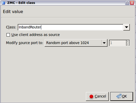
InbandRouter determines the target address from information embedded in the transferred protocol. This is possible only for protocols that can have routing information within the data stream. Application-level Gateway can use InbandRouter with the HTTP and FTP protocols. InbandRouter has the following options.
By default, Application-level Gateway uses its own IP address in the server-side connections: the server does not see the IP address of the original client. By selecting this option, Application-level Gateway mimics the original address of the client. Use this option if the server uses IP-based authentication, or the address of the client must appear in the server logs.
| Note |
|---|
This option was called Forge address in earlier versions of PNS. |
| Note |
|---|
The IP address of the client is related to the source NAT (SNAT) policy used for the service: using SNAT automatically enables the Use client address as source option in the router. |
This option defines the source port that Application-level Gateway uses in the server-side connection. The following options are available:
Random port above 1024: Selected a random port between 1024 and 65535. This is the default behavior of every router.
Random port in the same group: Select a random port in the same group as the port used by the client. The following groups are defined: 0-513, 514-1024, 1025–.
Client port: Use the same port as the client.
Specified port: Use the port set in the spinbutton.
| Note |
|---|
This option was called Forge port in earlier versions of PNS. |
ConnectChainer attempts to connect the destination defined by the router. It terminates the connection if the destination server is unreachable. ConnectChainer has the following options.
Assume that the server is unreachable if it cannot be connected for Connection timeout seconds.
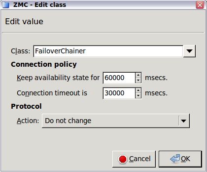
FailoverChainer is similar to ConnectChainer, and attempts to connect the destination defined by the router. However, if the destination is unreachable and the service uses DirectedRouter, Application-level Gateway attempts to connect the next destination set in the router.
| Tip |
|---|
FailoverChainer can be used to implement a simple high availability support for the protected servers. |
FailoverChainer has the following options.
Application-level Gateway does not try to connect to an unreachable server until the time set in the Keep availability state for option expires.
Assume that the server is unreachable if it cannot be connected for Connection timeout seconds.
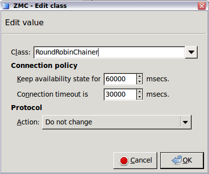
RoundRobinChainer is similar to FailoverChainer, but Application-level Gateway directs each incoming connection to the next available server. That way the load is balanced between the servers set in the destination list of the router. Use RoundRobinChainer together with DirectedRouter.
| Tip |
|---|
RoundRobinChainer can be used to implement simple load balancing for the protected servers. |
RoundRobinChainer has the following options.
Application-level Gateway does not try to connect to an unreachable server until the time set in the Keep availability state for option expires.
Assume that the server is unreachable if it cannot be connected for Connection timeout seconds.
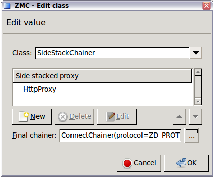
SidestackChainer does not connect to the server, but passes the traffic to the specified proxy. It is possible to sidestack several proxies that way. Application-level Gateway connects to the server using a regular chainer after the proxy processes the traffic. SidestackChainer has the following options.
The proxy class that will process the traffic. To select a proxy, click , select a proxy class, then click .
Application-level Gateway firewall rules are managed on the page. The following information is displayed for every rule:
| Note |
|---|
Not every column is displayed by default. To show or hide a particular column, right-click on the header of the table and select the column from the menu. |
: Shows if the rule is enabled or disabled.
: The unique ID number of the firewall rule.
: The tags (labels) assigned to the firewall rule. For details on assigning tags to rules, see Procedure 6.5.5, Tagging firewall rules.
: The transport protocol used in the connection. This is the protocol used in the transport layer (Layer 4) of the OSI model. For example, TCP, UDP, ICMP, and so on.
: The rule permits traffic only from the listed VPN connections (or IPSec connections with the specified Request ID).
: The rule permits traffic only for the clients of the listed zones and subnets.
: The rule permits traffic only for connections targeting the listed ports of the firewall host.
: The rule permits traffic only for connections that target addresses of the listed zones and subnets.
: The rule permits traffic only for connections that target an existing IP address of the selected interface (or interface group) of the firewall host. This parameter can be used to provide nontransparent service on an interface that received its IP address dynamically.
: The rule permits traffic only for connections that target the listed ports of the destination address.
: The name of the service used to inspect the traffic.
: The service started by the rule belongs to the instance shown.
: The description of the rule.
When Application-level Gateway receives a connection request from a client, it tries to select a rule matching the parameters of the connection. The following parameters are considered.
| Name in MC | Name in policy.py |
|---|---|
| VPN | reqid |
| Source Interface | src_iface |
| Source Interface Group | src_ifgroup |
| Protocol | proto |
| Source Port | src_port |
| Destination Port | dst_port |
| Source Subnet | src_subnet |
| Source Zone | src_zone |
| Destination Subnet | dst_subnet |
| Destination Interface | dst_iface |
| Destination Interface Group | dst_ifgroup |
| Destination Zone | dst_zone |
Table 6.1. Evaluated Rule parameters
Application-level Gateway selects the rule that most specifically matches the connection. Selecting the most specific rule is based on the following method.
The order of the rules is not important.
The parameters of the connection act as filters: if you do not set any parameters, the rule will match any connection.
-
If multiple connections would match a connection, the rule with the most-specific match is selected.
For example, you have configured two rules: the first has the
Source Zoneparameter set as theoffice(which is a zone covering all of your client IP addresses), the second has theSource Subnetparameter set as192.168.15.15/32. The other parameters of the rules are the same. If a connection request arrives from the192.168.15.15/32address, Application-level Gateway will select the second rule. The first rule will match every other client request. Application-level Gateway considers the parameters of a connection in groups. The first group is the least-specific, the last one is the most-specific. The parameter groups are listed below.
The parameter groups are linked with a logical AND operator: if parameters of multiple groups are set in a rule, the connection request must match a parameter of every group. For example, if both the
Source InterfaceandDestination Portis set, the connection must match both parameters.-
Parameters within the same group are linked with a logical OR operator: if multiple parameters of a group are set for a rule, the connection must match any one of the parameters. If there are multiple similar rules, the rule with the most-specific parameter match for the connection will be selected.
Note In general, avoid using multiple parameters of the same group in one rule, as it may lead to undesired side-effects. Use only the most-specific parameter matching your requirements.
For example, suppose that you have a rule with the
Destination Zoneparameter set, and you want to create a similar rule for a specific subnet of this zone. In this case, create a new rule with theDestination Subnetparameter set, do not set theDestination Zoneparameter in both rules. Setting theDestination Zoneparameter in both rules and setting theDestination Subnetparameter in the second rule would work for connections targeting the specified subnet, but it would cause Application-level Gateway to reject the connections that target other subnets of the specified destination zone, because both rules would match for the connection. -
The parameter groups are the following from least-specific to most-specific. Parameters within each group are listed from left-to-right from least-specific to most-specific.
Destination Zone>Destination Interface Group>Destination Interface>Destination SubnetSource Zone>Source SubnetDestination Port(Note that port is more specific than port range.)Source Port(Note that port is more specific than port range.)ProtocolSource Interface Group>Source Interface>VPN
-
If no matching rule is found, Application-level Gateway rejects the connection.
Note It is possible to create rules that are very similar, making debugging difficult.
Application-level Gateway can handle traffic both transparently and non-transparently. In transparent mode, the clients address the destination servers directly, without being aware that the traffic is handled by Application-level Gateway. In nontransparent mode, the clients address Application-level Gateway, that is, the destination address of the client's connection is an IP address of the firewall host, and Application-level Gateway determines the address of the destination server.
There are two methods to determine the destination address in nontransparent mode:
Inband destination selection: Application-level Gateway can extract the destination address from the incoming traffic itself. This method is currently supported for HTTP and FTP connections. For examples, see Section 6.5.6, Configuring nontransparent rules with inband destination selection.
Redirection: Application-level Gateway can redirect the traffic to a fix destination address.
6.5.3. Procedure – Finding firewall rules
Navigate to the Firewall Rules tab of the Application-level Gateway MC component.
-
Use the filter bar above the rule list to find rules. The use of the filter bar is described in Section 3.3.10, Filtering list entries. You can search for the parameters listed in Section 6.5.1, Understanding Application-level Gateway firewall rules.
-
Press . The rules matching your search criteria are displayed.
Note To save the list of matching rules into a file, click . Note that only the visible columns will be included in the file, in the order they are displayed.
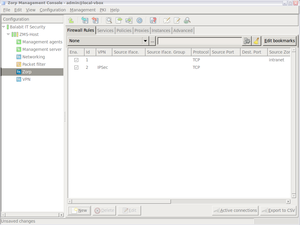
6.5.4. Procedure – Creating firewall rules
Purpose:
Firewall rules allow a specific type of traffic to pass the firewall. To create a new firewall rule, complete the following steps.
Steps:
-
Login to MS and select . A new window opens.
-
Select the tab.
-
Select the used in the connection. This is the protocol used in the transport layer (Layer 4) of the OSI model. The following protocols are supported:
TCP,UDP,ICMP,IGMP,DCCP,GRE,ESP,AH,SCTP, andUDP-Lite.To permit both TCP and UDP traffic, select .
To permit any Layer 4 protocol, select .
For ICMP traffic, you can specify the permitted type and subtype (code) as well.
-
Select the sources. Application-level Gateway can limit the traffic that can pass the firewall only to traffic that comes from selected source networks. To permit traffic only from specific networks, select . You can select zones, IPv4 or IPv6 subnets, interfaces, interface groups, and ports. Use always the most specific source suitable for your rule.
Note To specify multiple ports, separate the ports with a comma, for example:
80,443To specify a port range, use a colon, for example:
2000:2100To specify multiple port ranges, separate the port ranges with commas, for example:
2000:2100,2200:2400. -
Select the destinations. Application-level Gateway can limit the traffic that can pass the firewall only to traffic that is targeting selected destination addresses. To permit traffic only to specific networks, select . You can select zones, IPv4 or IPv6 subnets, interfaces, interface groups, and ports. Use always the most specific destination suitable for your rule.
Note For rules that start nontransparent services, set the destination address and the port to an address of the firewall host.
Note To specify multiple ports, separate the ports with a comma, for example:
80,443To specify a port range, use a colon, for example:
2000:2100To specify multiple port ranges, separate the port ranges with commas, for example:
2000:2100,2200:2400.Note Starting with Application-level Gateway 3 F5, it is not mandatory to set the sources and destinations. Sources and destinations act as a filter, they limit access to the clients or servers of the sources and destinations. A firewall rule without sources and destinations acts as a rule that simply forwards traffic between any client and destination.
-
Select the service to use. Select and select the service to start for connections matching the rule. The service determines type of traffic that will be permitted by this rule (for example, HTTP, FTP, and so on) and also the level the traffic will be inspected (application or packet-filter level).
Note Proxy services can be used only if the option is set to
TCP,UDP, orTCP or UDP.Warning The settings and parameters of the service shown on the tab of the rule are for reference only. Do not modify them, because it might interfere with other rules using the same service. To modify the parameters of a service, or to create a new service, use the tab of the MC component.
Select the instance the service should run in.
Optional Step: By default, new rules become active when the configuration is applied. To create a rule without activating it, deselect the option of the rule.
Optional Step: To limit the number of connections that can be started by the rule, configure rate limits for the connections. For details, see Procedure 6.5.7, Connection rate limiting.
-
Click , then commit your changes.
Expected result:
A new firewall rule is created and added to the list of firewall rules. If the rule is active, the traffic specified in the rule can pass the firewall.
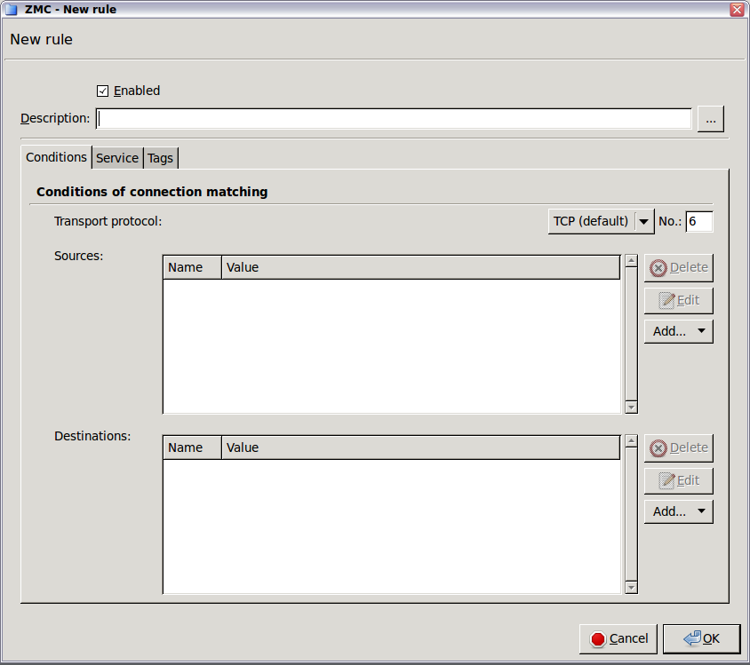
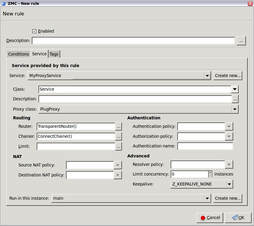
6.5.5. Procedure – Tagging firewall rules
Purpose:
To add a tag to a firewall rule, complete the following steps. Tagging rules is useful, for example, to identify rules that belong to the same type of traffic.
Steps:
Navigate to .
-
Select the rule to tag and click
-
Click . The list of available tags is displayed on the left; the tags assigned to the rule are displayed on the right.
To create a new tag, click , enter the name of the tag, then click .
To assign a tag to the rule, select a tag and click .
Note Tags that are already assigned to the rule are not shown in the list.
-
Click , then commit your changes.
Expected result:
The selected tags are assigned to the rule.
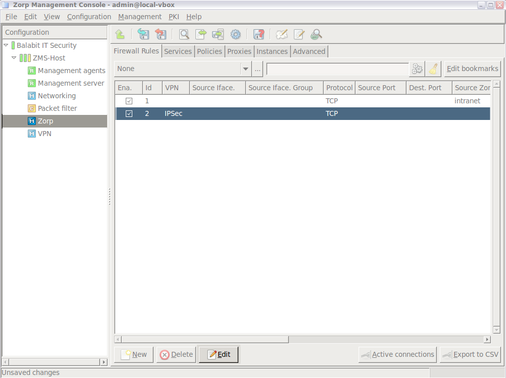
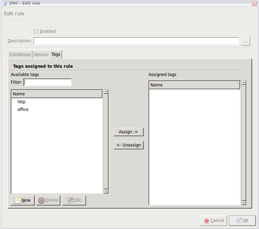
When using inband destination selection, Application-level Gateway extracts the address of the destination server from the traffic. Note the following points:
For HTTP connections, create a firewall rule that uses a nontransparent HTTP proxy and inband destination selection. Also, set the web browsers of the clients to use Application-level Gateway as a web proxy.
-
If the clients use a caching web proxy for HTTP traffic, for example, Squid, and Application-level Gateway is located between the clients and the web proxy, then:
Create a firewall rule that uses a nontransparent HTTP proxy.
Set the
parent_proxyandparent_proxy_portattributes of the proxy to the address of the caching proxy.Use a DirectedRouter in the service to redirect the connections to the caching proxy, or use inband destination selection.
6.5.7. Procedure – Connection rate limiting
Purpose:
To limit the maximum rate of new connections to prevent Denial of Service (DoS) attacks, configure the connection rate limiting options on the tab of the firewall rule. You can specify the number of connections that Application-level Gateway accepts within a given time period. Connection requests above this maximum rate are denied.
Steps:
Navigate to .
Select the rule to edit, then click
-
Click , then set the maximum number of permitted connection requests (per second) in the field.
To limit the rate of connections based on the destination in the connection requests, select .
To limit the rate of connections based on the source of the connection requests, select .
Set other parameters as needed for your environment.
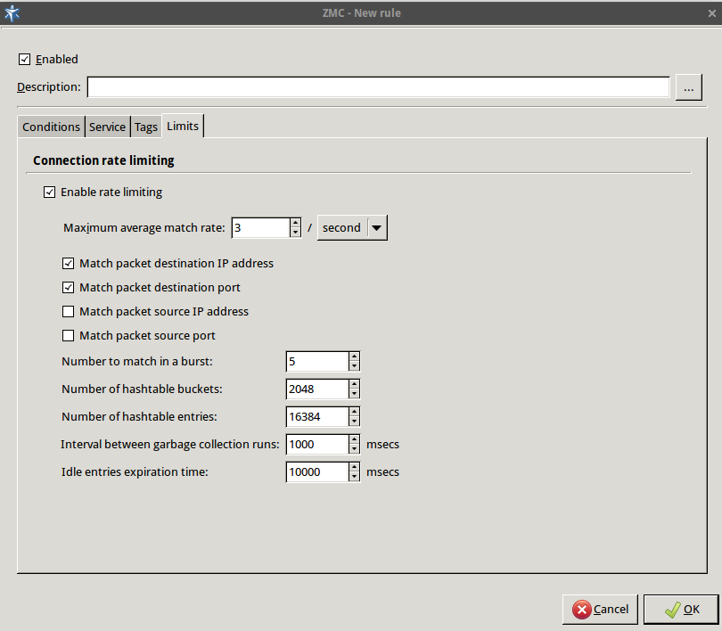
A proxy component is responsible for analyzing, filtering and possibly modifying the data that is passed through it.
Proxies work with data streams they receive as input and emit another (possibly altered) data stream as output. They never actually see “traffic” in the traditional sense; the details of connection establishment and management are handled by separate software components. Therefore, proxies can easily interoperate with each other or with other non-firewall software like virus filters, since data is passed among them as simple data stream.
A proxy class is the low level proxy and its configuration settings. Proxy classes are responsible for analyzing and checking the data part of packets and passing it between the client and the server. Proxy classes can be used in service definitions. Together with the other components configured as service parameters (for example, routers) they can be used to analyze/filter communication channels among network hosts. Most proxy classes are protocol-specific, meaning that they are aware of the protocol-specific information within the data stream they are processing.
There are built-in proxy classes for the most typical network traffic types, like HTTP, FTP, POP3, SMTP, telnet, and also for some less frequently used protocols, like NNTP and LDAP. They can be used in service definitions without modifications of the default class properties and their values. See the Proxedo Network Security Suite 1.0 Reference Guide for details.
| Note |
|---|
Proxies in Application-level Gateway are fully RFC-compliant so a traffic that pretends to be of a certain type but violates RFC specifications concerning the given traffic type are not proxied but automatically denied instead. For example, the HTTP proxy enforces by default the RFCs for HTTP (2616 and 1945). |
If using default proxy classes and property values is not enough, it is possible to derive new classes from the original ones. Derived proxy classes inherit all the properties of the original (parent) classes and these properties can then be altered. The number of configurable parameters varies among proxies; proxy for HTTP traffic has the most. It is completely up to you whether you use them in your firewall's policy settings.
| Note |
|---|
Whenever you start customizing a proxy, you do not actually create a new proxy, but derive a proxy class from the selected built-in proxy implementation and configure different settings for it. You only modify the configuration, not the proxy module itself. |
Default proxy classes provide an adequate level of security. You typically derive your own classes if you want to change the values of certain attributes, like manually setting the contents (like browser type, operating system) of the request headers leaving the HTTP proxy. Complex proxy setups – such as virus filtering of HTTP, SMTP, traffic or proxy stacking – also require derived classes.
This process is somewhat complex involving many steps; therefore will be demonstrated using an example of changing the User-Agent HTTP request header output by a custom HTTP proxy component.
The customized proxy class you are defining is based on an already defined proxy class. There are quite a lot of predefined proxy classes that are available by default. For some protocols (for example HTTP and FTP) there are more than one to choose from, each with a specific intended purpose. FtpProxyRO, for instance, is for read-only FTP access, while FtpProxyRW is for read/write FTP access.
6.6.1.1. Procedure – Derive a new proxy class
-
Select the tab of the
Application-level Gatewaycomponent.The Application-level Gateway class configuration window that appears is, by default, empty.
Click .
-
Select a predefined proxy class template for the customized proxy class.
Proxy class names are typically descriptive, but most of them comes with a detailed description as well. For more details, see the Proxedo Network Security Suite 1.0 Reference Guide. These descriptions either explicitly tell what the given proxy class is for or suggest attributes of the class that can be configured to achieve a special purpose.
Enter a name for the new proxy. You are recommended to use capital names that imply the functions the proxy is responsible for, for example
VirusHTTPorHTTPSproxy.-
Add the attributes to be configured and modify attribute values for the given class. For details, see Procedure 6.6.1.2, Customizing proxy attributes.
Note To have the new proxy class fully functional, you have to configure it as a service parameter of the given service.
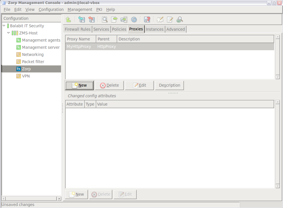
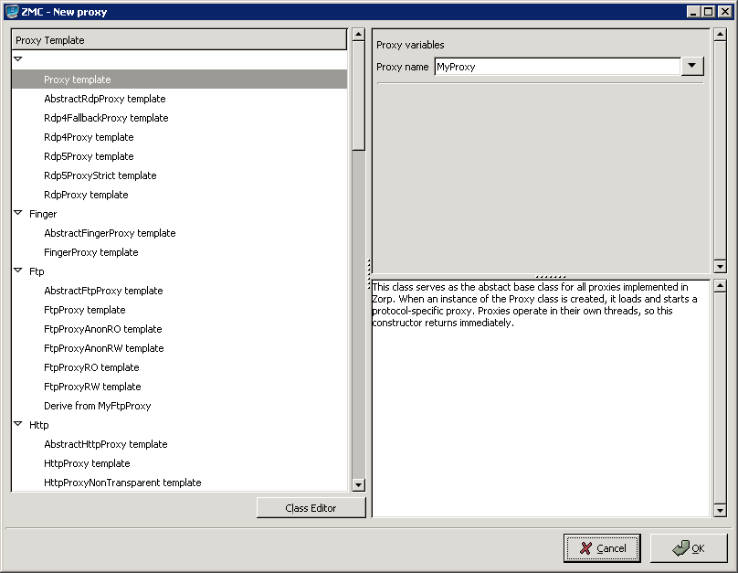
6.6.1.2. Procedure – Customizing proxy attributes
What attribute-level configuration is needed depends on the exact requirements: if you simply need an FTP proxy that denies upload (write) requests, use the FtpProxyRO without modifications in your policy definitions – deriving a new class is unnecessary in this case.
However, if you would like to hide the browser type and operating system version information of your clients you can do it with a derived proxy class, by customizing some of its attributes. To hide browser type and operating system version information for instance, the creation of a custom User-Agent header is required. Although this may be accomplished on the client side (modifying all client web browsers), it is much easier to do with PNS.
The attributes configuration screen is divided into two main parts.
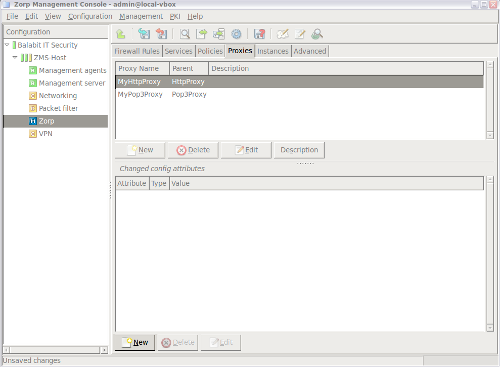
The upper textbox shows the list of custom, derived proxies along with the classes they were derived from (the Parent column). For the previous screenshot a simple HttpProxy, called MyHttpProxy was derived from the generic HttpProxy class.
Navigate to and select the proxy to customize.
-
Click under the lower table. The list of configurable attributes are displayed.
Note A short description for each attribute is also displayed. For a complete description of proxy classes and attributes see the Proxedo Network Security Suite 1.0 Reference Guide.
There are syntax rules for setting attributes properly. For more information on these rules, see the Proxedo Network Security Suite 1.0 Reference Guide or, to a limited extent, read all the available descriptions on the class selection screen.
Tip AbstractProxy template descriptions are especially useful, since they contain the most information on syntax. For example, to set HTTP request headers in the traffic, see Section 4.7.2.2, Configuring policies for HTTP requests and responses in Proxedo Network Security Suite 1.0 Reference Guide.
-
Select
self.request_headerattribute.The attribute appears in the listing of the Application-level Gateway class configuration screen.
-
Set the value of the attribute by clicking . (Attribute Type is less relevant now.) A new window opens which is, by default, empty.
-
Click the button to define the name of the parameter you want to change.
In this example HTTP request headers are configured. These are standardized in the corresponding RFC documentation or in any reliable book on web server administration/programming.
One of the request headers is called
User-Agentwhich is the place to specify browser type and version and operating system information. Popular statistics, such as the market share of web browsers, are based on this request header.By default, Application-level Gateway takes the original
User-Agentheader information it receives from clients and uses the same value in http requests it generates. -
Enter
User-Agentin the small dialog box to change the default behavior.You can see the name of the header changing (Key column), but Type and Value columns still need to be changed.
-
Left-click on the column of the row containing the previously entered
User-Agentstring. A drop-down list appears. Remember, you are changing the value of an existing attribute, so selecttype_http_hdr_change_valuehere which changes the given header values. -
Click to modify the Value column.
Set the actual value of the
User-Agentrequest header. The following window opens.This window represents another view of the attribute you are modifying now. The Type column of Figure Selecting action type for the attribute is now the first row in this window, while the Value column became the second row here; it is currently empty.
-
Click to set the Value column and enter a string.
A string can be for example,
My Browser.Note Web servers you visit from now on will see this information as the
User-Agentheader they receive and may act strangely if they, or the content they serve (Java Servlets, for instance) are not prepared to handle unexpected values inUser-Agentheaders. -
The process of changing the desired proxy class attribute is complete, you can see the result in the Application-level Gateway class configuration window.
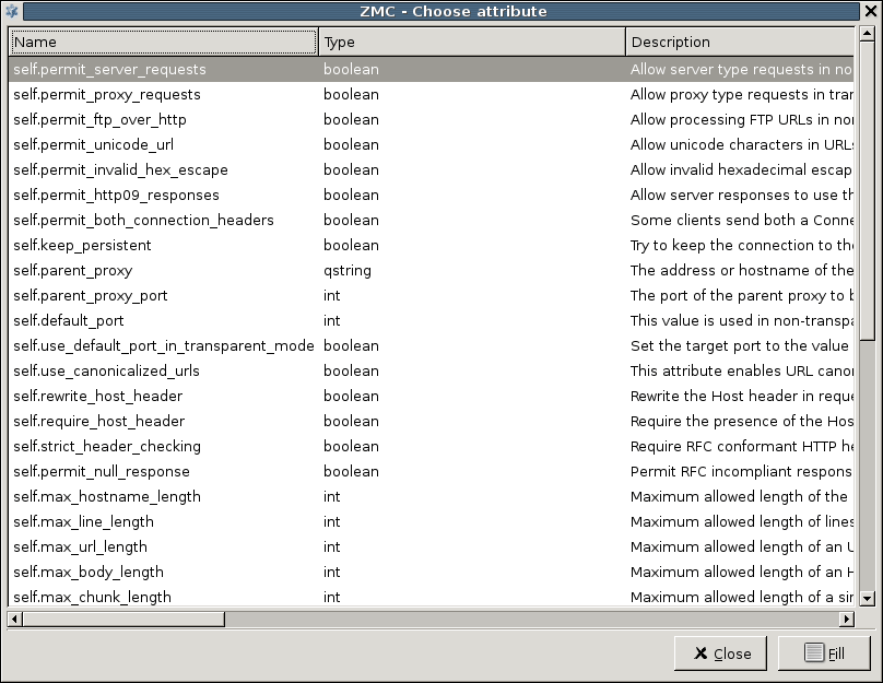
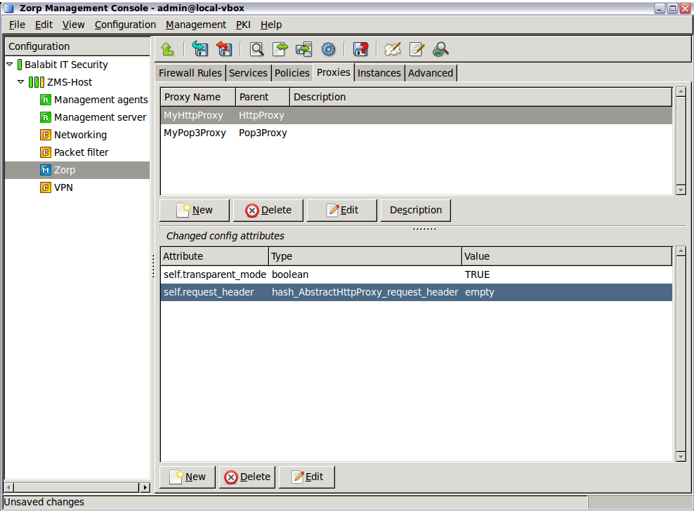
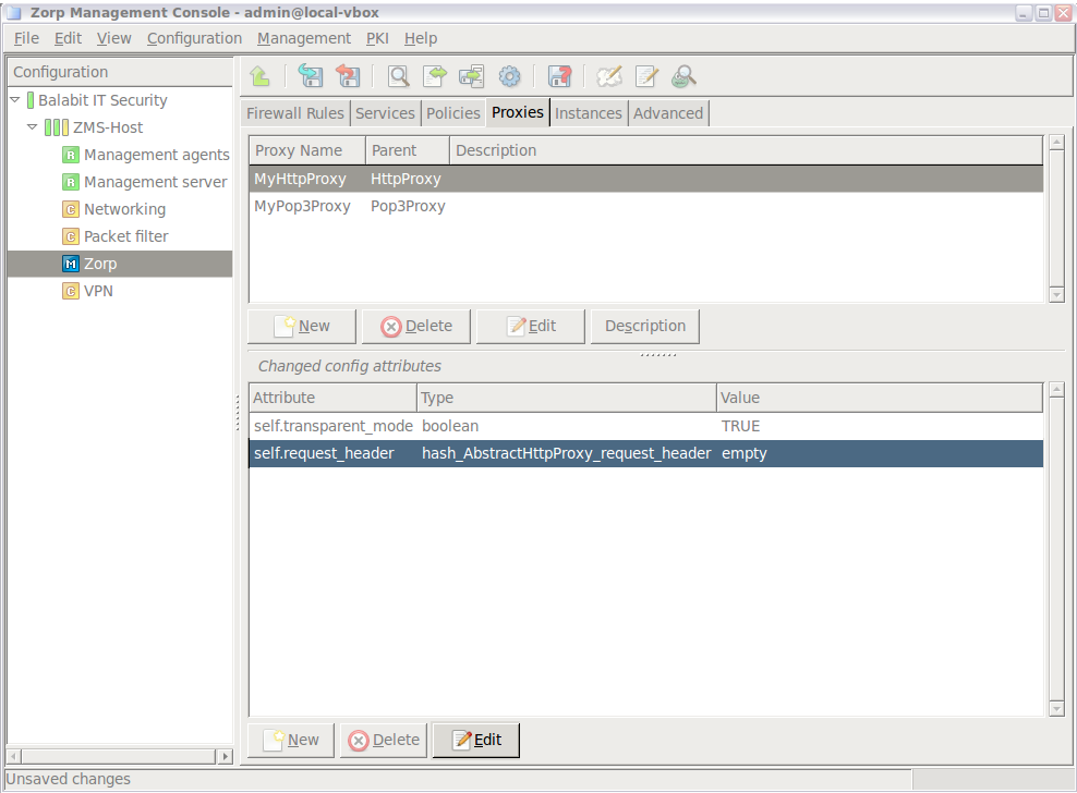
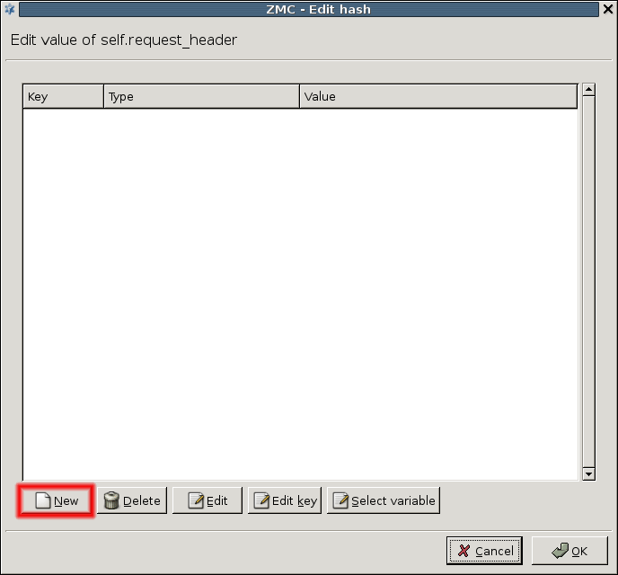
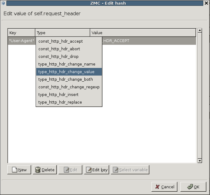
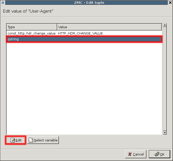
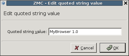
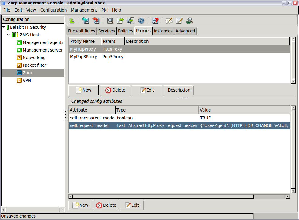
The parameter configured in the service definition defines what traffic passes through with the help of the given service. Different services can have different es configured, even for the same traffic type. For example, a firewall can have a number of services configured to pass HTTP traffic, each with its own, derived and customized proxy class parameter. If these es are parameterized differently, the corresponding services also behave differently for the same HTTP traffic. A single service can only have a single value configured, although that proxy class parameter can refer to a stacked proxy setup as well.
6.6.2. Procedure – Renaming and editing proxy classes
To modify the basic attributes, for example, the name and the parent class of a proxy, complete the following steps:
Select the class and click .
To rename the class, edit the name of the proxy in the field, then click .
-
To modify the parent class of the proxy, select the new class from the tree on the left of the dialog, then click .
Warning As a result of modifying the parent class, an already configured proxy (that is, one that had its default values or attributes modified) looses the attributes not present in its new parent class.
Most Application-level Gateway proxies can pass the information received as the payload of the incoming traffic to another proxy for further analysis. This kind of complex data analysis is possible by placing a proxy inside another one. This process is called stacking. Stacking is especially useful in filtering compound traffic, a traffic that consists of two (or more) protocols or that needs to be analyzed in two different ways.
| Note |
|---|
Earlier versions of Application-level Gateway used stacking to inspect encrypted protocols, for example, HTTPS or IMAPS. Now every proxy can decrypt SSL and TLS encryption without having to use another proxy. For details on configuring Application-level Gateway to handle encrypted connections, see How to configure SSL proxying in PNS 1.0. |
Usually protocols consist of two parts:
control information, and
data.
Protocol proxies analyze and filter the control part and except for some cases they are unaware of the data part. At this point, further screening of the data might be needed, therefore proxies are able to stack in other proxies capable of filtering the data part, so the external (upper) proxy passes that data traffic to the internal (lower) proxy.
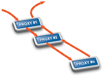
| Example 6.8. Virus filtering and stacked proxies |
|---|
|
Virus filtering is also a multiple analysis of traffic. This is typically performed in HTTP, POP3 and SMTP traffic, because these are the protocols viruses generally use for spreading over the Internet (using Application-level Gateway it is possible to filter for viruses in other protocols as well). When virus filtering is configured, a standard protocol proxy works in tandem with an antivirus engine and in this way both protocol specific and virus filtering is performed on the data if you stack the antivirus engine into some proxy. For details on configuring virus filtering in HTTP and HTTPS traffic, see How to configure virus filtering in HTTP. |
For each stacking scenarios there are a number of attributes that can be configured. For more information see the Proxedo Network Security Suite 1.0 Reference Guide.
6.6.3.1. Procedure – Stack proxies
Since Application-level Gateway proxies natively support TLS-encrypted connections, stacking proxies is rarely needed in Application-level Gateway. For details on configuring TLS-encrypted connections (for example, HTTPS), see How to configure SSL proxying in PNS 1.0. If you need to stack proxies for some reason, complete the following steps.
Derive a proxy class from one of the predefined ones. For details, see Section 6.6.1, Customizing proxies.
Derive a proxy class for the 'external' or parent proxy.
-
Configure stacking on the Application-level Gateway Class configuration screen.
Configuring stacking essentially means setting an attribute of the container proxy. The exact name of the attribute depends on the parent proxy. For details, see the Proxedo Network Security Suite 1.0 Reference Guide. For details on setting proxy attributes, see Procedure 6.6.1.2, Customizing proxy attributes.
The tab provides a single interface for managing all the different policies used in Application-level Gateway service definitions.
Policies are independent from service definitions. A single policy can be used in several services or proxy classes. Policies must be created and properly configured before they are actually used in a service. When configuring a service, only the existing (that is, previously defined) policies can be selected.
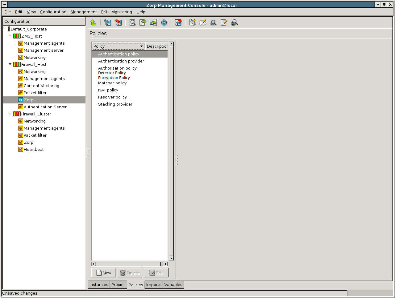
On the left side of the Policies tab the existing policies are displayed in a tree, sorted by policy type. If a policy is selected, its parameters are displayed on the right side of the panel.
The policies available from the tab of the MC component are listed below. The subsequent sections describe the different policy types and their uses. The Authentication, Authentication Provider, and Authorization policies are discussed in Chapter 15, Connection authentication and authorization.
NAT Policy: Policies for source and destination network address translation.
Authentication Policy: Policies describing how clients should be authenticated in different scenarios. See Chapter 15, Connection authentication and authorization for details.
Authentication Provider: AS authentication backends: databases providing user information for authentication. See Chapter 15, Connection authentication and authorization for details.
Authorization Policy: Policies describing how clients should be authorized in different scenarios. See Chapter 15, Connection authentication and authorization for details.
Detector Policy: Policies that start a service based on the protocol used in the connection.
Matcher Policy: Various matcher and filtering policies.
Resolver Policy: Simple domain name resolution policies.
Stacking Provider: External PNS hosts providing content filtering capabilities.
6.7.1. Procedure – Creating and managing policies
To create a new policy, complete the following steps.
Navigate to and click the button under the policies list.
-
Enter a name for the policy and select the type of the new policy from combobox. If a policy or a policy group (for example, NAT policy) is selected, the combobox is automatically set to the same type.
Note Custom policy classes can be created using the . However, this is only recommended for advanced users.
-
Configure the parameters of the new class on the right side of the panel. Existing policy classes can be modified here as well.
Tip To disable a policy or a matcher, use the local menu (right-click the selected policy). Disabled policies will be generated into the configuration files as comments.
To duplicate a policy, use the and options of the local or the menu.
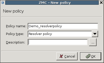
Detector policies can be used in firewall rules with DetectorServices: they specify which service should Application-level Gateway start for a specific type of protocol or certificate found in the traffic of connection. Currently Detector policies cam detect the HTTP, SSH, and SSL protocols. In SSL/TLS-encrypted connections, Application-level Gateway can select which service to start based on the certificate of the server.
For example, you can use this feature for the following purposes:
enable HTTP traffic on non-standard ports
enable SSL-encrypted traffic only to specific servers or server farms that do not have public IP addresses (for example, Microsoft Windows Update servers)
enable access only to specific HTTPS services (for example, enable access to Google Search (which has a certificate issued to
www.google.com), but deny access to GMail (which uses a certificate issued toaccounts.google.com))
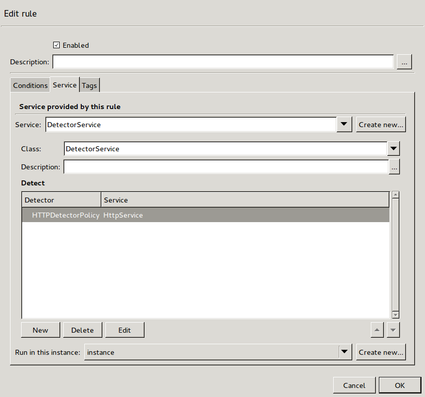
Detector policies contain a detector that determines if the traffic in a connection belongs to a particular protocol or not. Firewall rules can include a list of detector-service pairs. When a client opens a connection that is handled by a DetectorService, Application-level Gateway evaluates the detectors in the Detector policy of the DetectorService, starting with the first detector. When a detector matches the traffic in the connection, Application-level Gateway starts the service set for the detector to handle the connection. If none of the detectors match the traffic, then Application-level Gateway terminates the connection.
For a basic overview about Encryption policies, see Section 6.7.3.1, Understanding Encryption policies.
For examples on configuring Encryption policies, see How to configure SSL proxying in PNS 1.0. For details on HTTPS-specific problems and its solutions, see How to configure HTTPS proxying in PNS 1.0.
For details on how the SSL/TLS framework works in Application-level Gateway, see Chapter 3, The PNS SSL framework in Proxedo Network Security Suite 1.0 Reference Guide
This section describes the configuration blocks of Encryption policies and objects used in Encryption policies. Encryption policies were designed to be flexible, and make encryption settings easy to re-use in different services.
An Encryption policy is an object that has a unique name, and references a fully-configured encryption scenario.
Encryption scenarios are actually Python classes that describe how encryption is used in a particular connection, for example, both the server-side and the client-side connection is encrypted, or the connection uses a one-sided SSL connection, and so on. Encryption scenarios also reference other classes that contain the actual settings for the scenario. Depending on the scenario, the following classes can be set for the client-side, the server-side, or both.
-
Certificate generator: Creates or loads an X.509 certificate that Application-level Gateway shows to the peer. The certificate can be a simple certificate (Section 5.5.23, Class StaticCertificate in Proxedo Network Security Suite 1.0 Reference Guide), a dynamically generated certificate (for example, used in a keybridging scenario, Section 5.5.12, Class DynamicCertificate in Proxedo Network Security Suite 1.0 Reference Guide), or a list of certificates to support Server Name Indication (SNI, Section 5.5.17, Class SNIBasedCertificate in Proxedo Network Security Suite 1.0 Reference Guide).
Related parameters:
client_certificate_generator,server_certificate_generator -
Certificate verifier: The settings in this class determine if Application-level Gateway requests a certificate of the peer and how to verify it. Application-level Gateway has separate built-in classes for the client-side and the server-side verification settings: Section 5.5.6, Class ClientCertificateVerifier in Proxedo Network Security Suite 1.0 Reference Guide and Section 5.5.19, Class ServerCertificateVerifier in Proxedo Network Security Suite 1.0 Reference Guide. For details and examples, see Section 3.2.5, Certificate verification options in Proxedo Network Security Suite 1.0 Reference Guide.
Related parameters:
client_verify,server_verify -
Protocol settings: The settings in this class determine the protocol-level settings of the SSL/TLS connection, for example, the permitted ciphers and protocol versions, session-reuse settings, and so on. Application-level Gateway has separate built-in classes for the client-side and the server-side SSL/TLS settings: Section 5.5.10, Class ClientSSLOptions in Proxedo Network Security Suite 1.0 Reference Guide and Section 5.5.22, Class ServerSSLOptions in Proxedo Network Security Suite 1.0 Reference Guide. For details and examples, see Section 3.2.6, Protocol-level TLS settings in Proxedo Network Security Suite 1.0 Reference Guide.
Related parameters:
client_ssl_options,server_ssl_option
Application-level Gateway provides the following built-in encryption scenarios:
: Both the client-Application-level Gateway and the Application-level Gateway-server connections are encrypted. For details, see Section 5.5.24, Class TwoSidedEncryption in Proxedo Network Security Suite 1.0 Reference Guide.
: Only the client-Application-level Gateway connection is encrypted, the Application-level Gateway-server connection is not. For details, see Section 5.5.8, Class ClientOnlyEncryption in Proxedo Network Security Suite 1.0 Reference Guide.
: Only the Application-level Gateway-server connection is encrypted, the client-Application-level Gateway connection is not. For details, see Section 5.5.21, Class ServerOnlyEncryption in Proxedo Network Security Suite 1.0 Reference Guide.
: The client can optionally request STARTTLS encryption. For details, see Section 5.5.15, Class ForwardStartTLSEncryption in Proxedo Network Security Suite 1.0 Reference Guide.
: The client can optionally request STARTTLS encryption, but the server-side connection is always unencrypted. For details, see Section 5.5.9, Class ClientOnlyStartTLSEncryption in Proxedo Network Security Suite 1.0 Reference Guide.
: The client can optionally request STARTTLS encryption, but the server-side connection is always encrypted. For details, see Section 5.5.14, Class FakeStartTLSEncryption in Proxedo Network Security Suite 1.0 Reference Guide.
For examples on configuring Encryption policies, see How to configure SSL proxying in PNS 1.0. For details on HTTPS-specific problems and its solutions, see How to configure HTTPS proxying in PNS 1.0.
In general, matcher policies can be used to find out if a parameter is included in a list (or which elements of a list correspond to a certain parameter), and influence the behavior of the proxy class based on the results. Matchers can be used for a wide range of tasks, for example, to determine if the particular IP address or URL that a client is trying to access is on a black or whitelist, or to verify that a particular e-mail address is valid. The matchers usable in a proxy class are described in the Proxedo Network Security Suite 1.0 Reference Guide.
| Note |
|---|
Matchers can also be used in custom proxy classes created with the . |
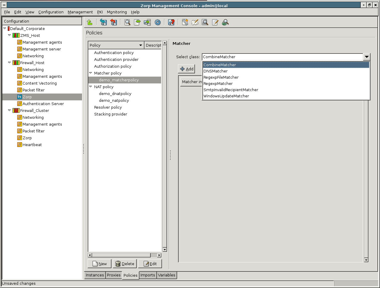
Application-level Gateway has a number of predefined matcher classes; and it is also possible to make complex decisions from the results of individual matchers using the CombineMatcher class. The available predefined classes are listed below.
DNSMatcher: Retrieves the IP address(es) of a domain from the name server specified.
WindowsUpdateMatcher: Retrieves the IP addresses required for updating computers running Microsoft Windows from the name server specified.
RegexpMatcher: General regular expression matcher.
RegexpFileMatcher: Regular expression based matching on the contents of files.
SmtpInvalidRecipientMatcher: Consults a mail server to verify that an e-mail address is valid.
CombineMatcher: Makes complex decisions by combining the results of multiple simple matchers using logical operations.
Apart from the predefined ones, it is also possible to create custom matcher classes. The various matcher classes and their uses are described in the subsequent sections. The use of matchers in proxy classes is discussed in Section 6.7.4.7, Using matcher classes in proxy classes.
DNSMatcher retrieves the IP addresses of domain names. This can be used in domain name based policy decisions, for example to allow encrypted connections only to trusted e-banking sites. If the IP address of the name server is not specified in the field, the name server set in the component is used (see Section 5.3, Managing client-side name resolution for details).
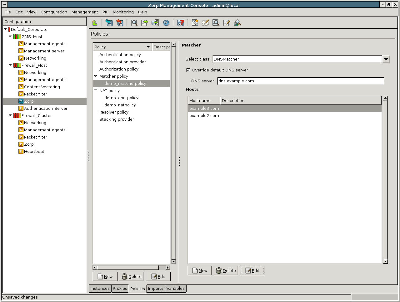
WindowsUpdateMatcher is actually a DNSMatcher used to retrieve the IP addresses currently associated with the v5.windowsupdate.microsoft.nsatc.net, v4.windowsupdate.microsoft.nsatc.net, and update.microsoft.nsatc.net domain names; only the IP address of the name server has to be specified. Windows Update is running on a distributed server farm, using the DNS round robin method and a short TTL to constantly change the set of servers currently visible, consequently the IP addresses of the servers are constantly changing.
| Tip |
|---|
This matcher class is useful to create firewall policies related to updating Windows-based machines. Windows Update is running over HTTPS. For example, there is no real use in inspecting the HTTP traffic embedded into the SSL tunnel (since it is mostly file download), but it is important to verify the identity of the servers. |
A RegexpMatcher consists of two string lists, describing the regular expressions to be found ( list) and, optionally, another list of expressions that should be ignored ( list) when processing the input. By default, matches are case insensitive. For case sensitive matches, uncheck the option.
| Note |
|---|
The string lists are stored in the |
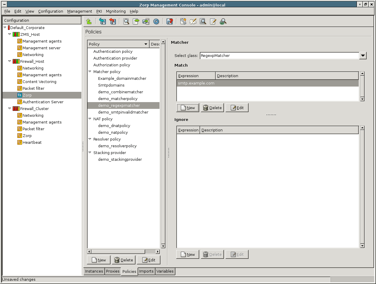
RegexpFileMatcher is similar to RegexpMatcher, only the two lists are stored in separate files. The matcher itself stores only the paths and the filenames to the lists. The files themselves can be managed either manually, or using the plugin.
This matcher class uses an external SMTP server to verify that a given address (that is, the recipient of an e-mail) exists. The following parameters have to be specified:
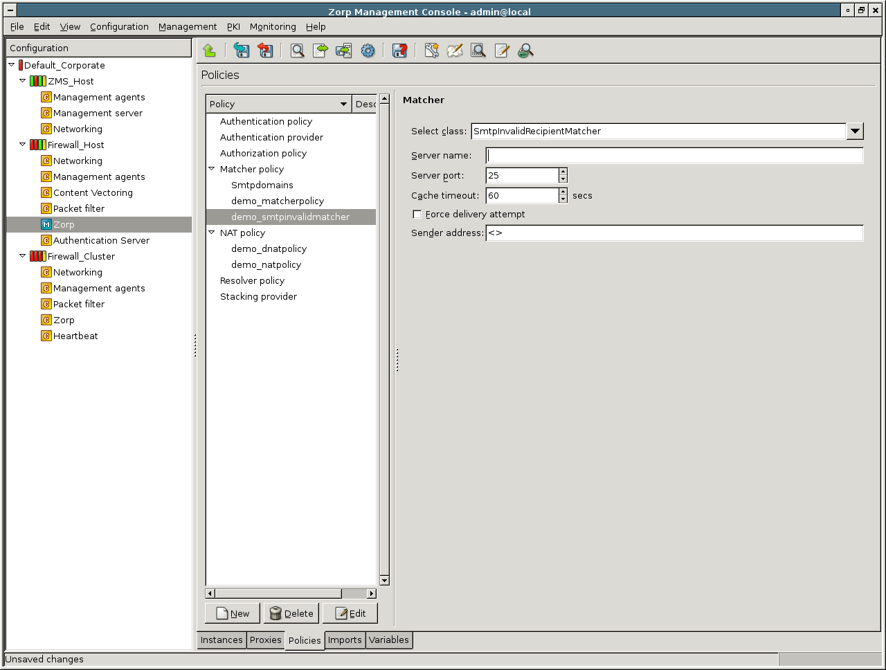
and : The domain name and the port used by the SMTP server to be queried.
: Application-level Gateway uses this IP address as the source address of the connection when connecting the SMTP server to be queried.
: The result of a query is stored for the period set as in seconds. If a new e-mail is sent to the same recipient within this interval, the stored verification result is used.
and : Send an e-mail to the recipient as if it was sent by . If the destination mail server accepts this mail, the original e-mail is sent. This option is required because many mail server implementations do not support the
VRFYSMTP command properly, or it is not enabled. (The default value for is<>, which refers to the mailer daemon and is recognized by virtually all servers.)
CombineMatcher uses the results of multiple matchers to make a decision. The results of the individual matchers can be combined using the logic operations AND, OR and NOT. Both existing matcher policies () and policies defined only within the particular CombineMatcher () can be used.
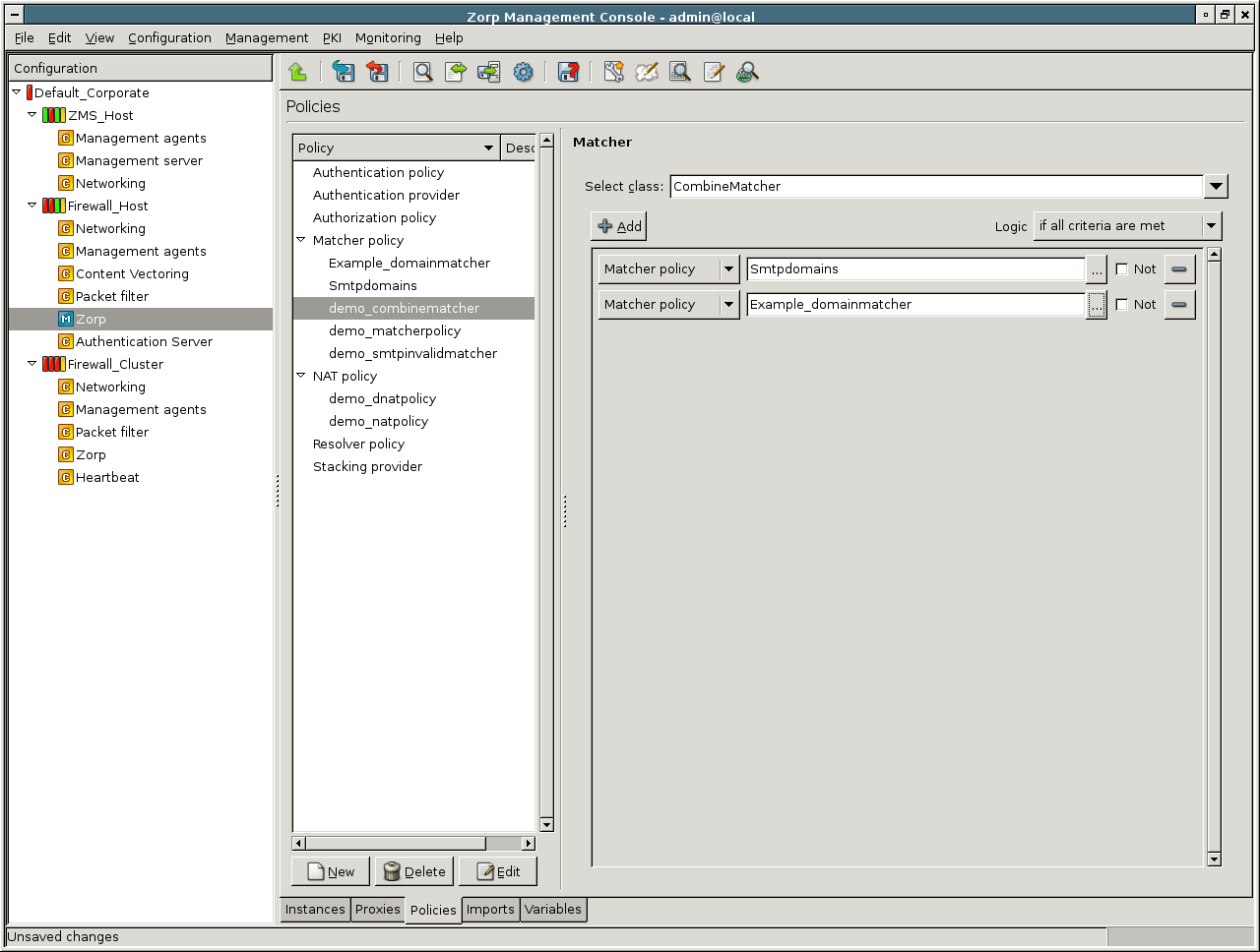
New matchers can be added with the button. Each line in the main window of the CombineMatcher configuration panel corresponds to a matcher. To use an existing matcher policy, set the combobox on the left to . After that, clicking the opens a dialog window where the matcher to be used can be selected.
| Tip |
|---|
Matchers can also be configured on-the-fly: set the combobox to , click on , and select and configure the matcher as required. |
Each matcher can be taken into consideration either with its regular, or with its inverted result using the checkbox. The individual matchers (or their inverses) can be combined with the logical AND, and OR operations. This can be set in the combobox:
: Corresponds to logical AND; the CombineMatcher will return the TRUE value only if all criteria are TRUE.
: Corresponds to logical OR; the CombineMatcher will return the TRUE value if at least one criteria is TRUE.
: CombineMatcher will return the TRUE value if all criteria have the same value (either TRUE or FALSE).
| Tip |
|---|
A CombineMatcher can also be used to combine the results of other CombineMatchers, thus very complex decisions can also be made. |
To actually use the defined matchers, they have to be specified in the proper attributes of the particular proxy class. The proxy classes can use matchers for a variety of tasks. The matchers to be used by the particular proxy class can be added as .
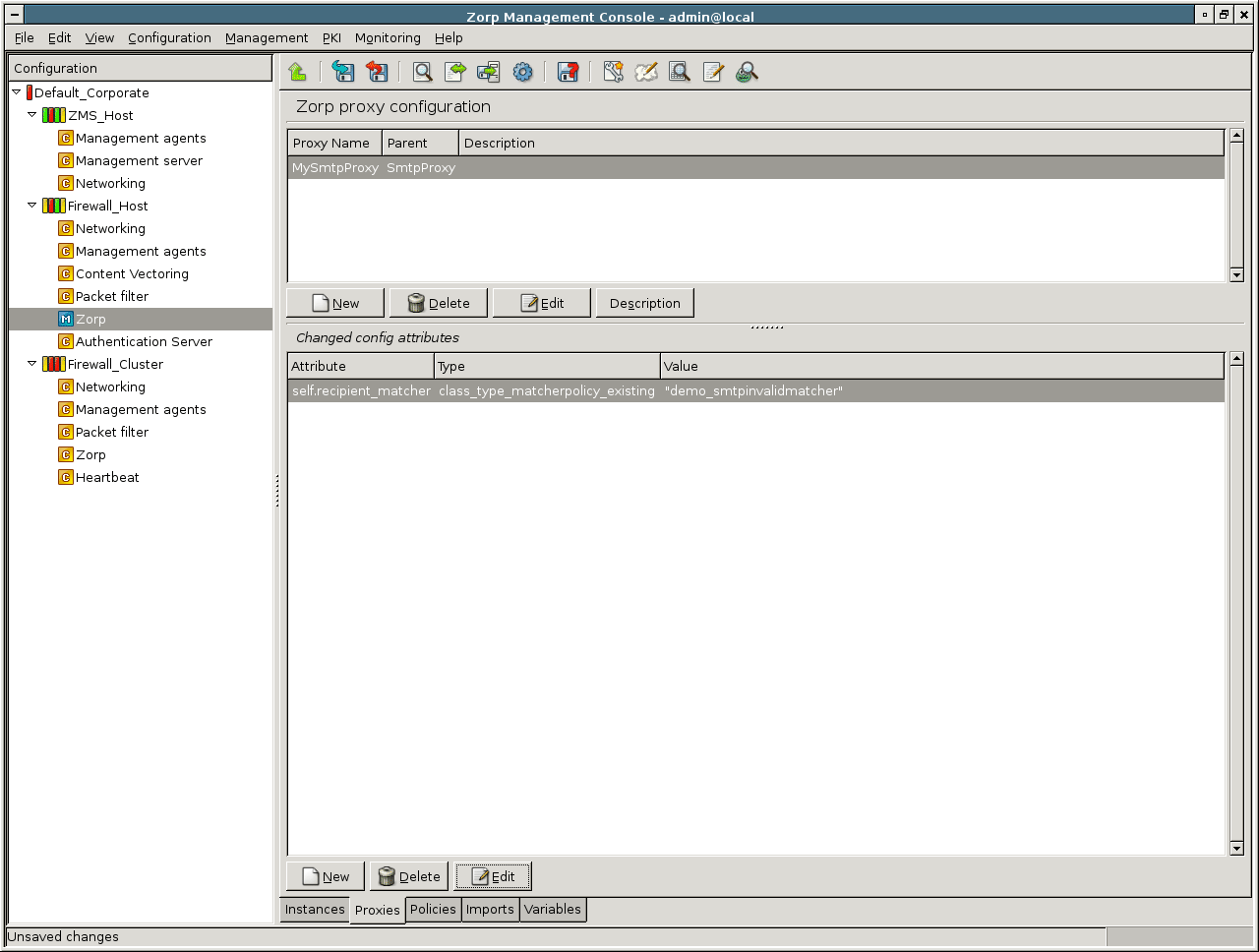
For example, SmtpProxy can use three different matchers: one to check the relayed domains (for example, using a RegexpMatcher), and two SmptInvalidMatchers (one for sender, one for the recipient address verification). For the details of the matchers usable by a given proxy class see the attributes of the class in Chapter 4, Proxies in Proxedo Network Security Suite 1.0 Reference Guide.
Network Address Translation (NAT) is a technology that can be used to change source or destination addresses in a connection from one IP address to another one.
Today most corporate networks work with private, non-Internet-routable IP addresses from the 10.0.0.0/8, 172.16.0.0/12 or 192.168.0.0/16 ranges. These IP addresses are suitable for intranet communication (they can even be routed internally) but cannot be used on the Internet. Therefore a mechanism, NAT, is in place that, whenever an internal client wants to access Internet resources, uses a public IP address for this purpose.
Another use for NAT is address hiding. Towards the Internet only a limited number of public IP addresses are visible, while you may have thousands of internal clients and servers all “translated” to those few addresses.
| Tip |
|---|
Address hiding with the help of NAT is especially useful for published servers (usually located in a DMZ). The potential attackers only see a few public IP addresses (or even a single one) but from this information they have no way of knowing where your servers are actually located, how many of them there are and in what configuration. |
| Note |
|---|
Although address hiding can be considered as a security feature, NAT alone is not enough to protect a network from malicious intruders. Never use NAT in itself as a security solution. |
Based on whether source or destination IP addresses are transformed two kinds of NAT can be differentiated.
-
Source NAT (SNAT),
if source IP addresses are transformed.
-
Destination NAT (DNAT),
if address transformation is performed on destination IP addresses.
Basically, NAT in Application-level Gateway provides a possibility to modify the source and destination IP address at the server side before the connection is established. The source and destination IP address values are defined previously by the router on the basis of router type, its settings and the client request. In some cases, Proxy settings can also be involved, for example when the router option is enabled. NAT is responsible for changing IP addresses to some other addresses depending on the configuration of the NAT policy.
| Note |
|---|
This NAT is performed by the component and is totally different from the NAT offered by IPTables in the component. |
By default, when no NAT policy is set up, Application-level Gateway uses its own IP address configured for the corresponding network interface when sending out traffic in any direction. Although this results in many clients “using” the same (single) IP address, it is not considered as SNAT technically.
In Application-level Gateway NAT is performed on the application proxy level. In this case it is not strictly IP address replacement, since original packets do not appear in the traffic leaving the firewall. It is an IP address modification rule rather. If application proxying is used — meaning there is no traffic that is forwarded on the packet filter level — packet filter level NAT is neither required nor recommended.
Service definitions contain NAT policy settings to configure application proxy–level NAT.
| Note |
|---|
|
If some traffic is managed at the packet filter level, NAT must be performed at the packet filter level, too. In this case, NAT is really IP address replacement, since the packet filter – rules permitting – forwards the original packets it receives. You are not recommended to use NAT at the packet filter level. For more details on packet filter-level NAT solutions, see Appendix A, Packet Filtering. |
Originally NAT meant only address translation, leaving port information travelling in TCP or UDP packets unmodified. This can lead to errors especially in large networks where thousands of clients are NATed by a single machine, therefore NAT technologies were modified to do port translation as well, guaranteeing that even if two internal clients try to use the same source port number in session establishments, the packets leaving the NAT server always have unique source IP address/port pairs.
| Note |
|---|
Port translating NAT devices are incompatible with IPSec encryption (which is a major drawback as IPSec is becoming increasingly popular) and may be incompatible with proprietary, two-channel protocols as well. |
Before you start NAT configuration you must decide whether you need it at all. If you need traffic redirection, for example a Web server in your DMZ, routers may serve your needs. By default, Application-level Gateway uses its own IP address (bound to the corresponding adapter) to all connections leaving it in any direction, unless the router option is set, in which case the original client IP address is used. Consequently, NAT may not be absolutely necessary.
| Note |
|---|
Configuring for a automatically enables the router function, so during SNAT the client's address is used, not the firewall's. |
Unlike in firewall-less network configurations, where NAT is a universal setting for all clients communicating with any protocol, in Application-level Gateway different traffic can be NATed differently because NAT configurations are linked to services. It can happen that while outgoing HTTP traffic is SNATed to a single public IP address, SQL traffic from the same network is not SNATed at all, and finally FTP download traffic is SNATed to a separate NAT pool.
6.7.5.1.1. Procedure – Configuring NAT
-
Create the required NAT policies on the tab of the MC component.
Click the button, select from the combobox and supply a name for the new policy.
Names should be descriptive and ideally contain information about the direction of NATing and/or about the type of traffic NATed.
In most network configurations NAT is typically not service-specific; a generic NAT policy may be adequate for most outgoing or incoming traffic. There are no compulsory rules for naming.
NAT policies can be renamed any time.
Tip Remove NAT policies from the configuration set if they are no longer needed.
NAT policies can be removed only if they are not used in any service definition.
-
Configure a NAT solution.
Application-level Gateway supports several different NAT solutions.
GeneralNAT has three parameters: source address, destination address, and the translated address. Connections arriving from the source address that target the destination address are modified to use the translated address. If the NAT policy is used as Source-NAT (SNAT), the source address is translated to the translated address, if the policy is used as Destination NAT (DNAT), the target address is translated.
Note The original and translated netmasks do not need to be the same: it is possible to map an entire /24 network onto a single IP address (/32 mask). However, the order of the pairs is important because the Application-level Gateway processes the list from top to bottom.
Depending on the NAT type (SNAT, DNAT), Application-level Gateway evaluates the NAT rules one after the other. If a row containing the address to be NATed as the source network, the iteration stops and Application-level Gateway modifies the IP address as specified in that row. If no match is found, the original IP address is used.
When modifying the address, it calculates the host ID of the address using the target netmask and the source network address and adds it to the target network.
-
Configure caching.
Since the NAT decision may take a long time in some cases (for example, if there are many mappings in the list), the decisions can be stored in a cache. Storing the decisons in a cache accelerates future decisions. Caching can be enabled/disabled using the checkbox in the configuration window of the NAT policy.
Tip It is recommended to enable caching for complex NAT decisions.
Note Enabling caching can have interesting, but sometimes unwanted effects on some NAT types, for example on
RandomNAT. UsingRandomNATand theCachableoption together would result in LoadBalancing, but with sticky IP addresses, the cache would remember which source IP address was used before for a specific client's IP address and would use the same address again. This can be very useful, but can also cause a lot of headache and troubleshooting.
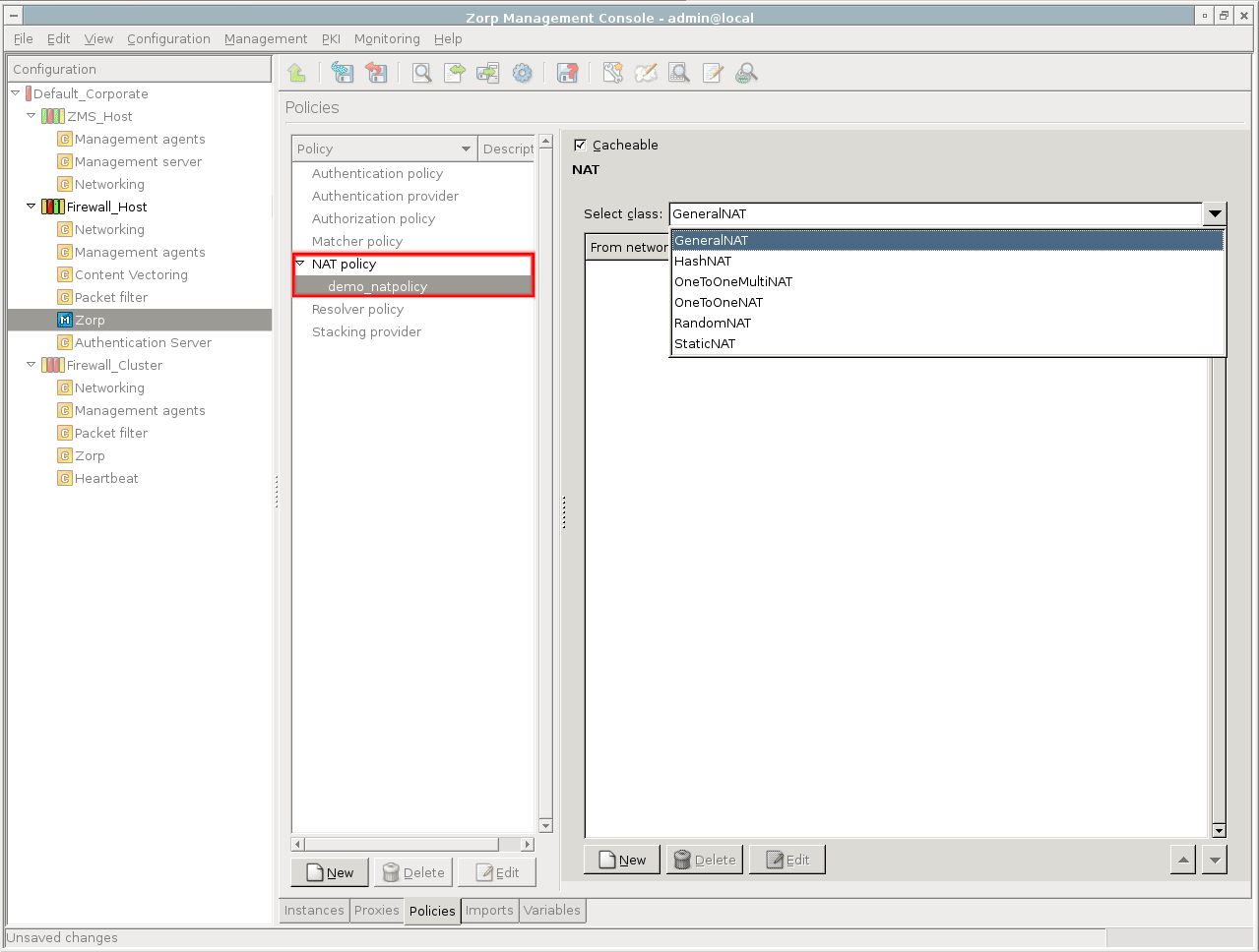
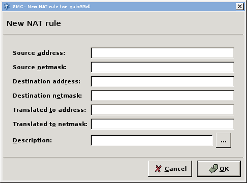
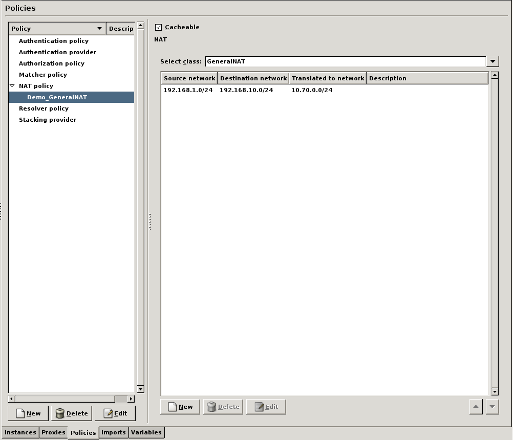
Application-level Gateway supports the following types of NAT policies. For details on the parameters of these NAT policies, see Section 5.8, Module NAT in Proxedo Network Security Suite 1.0 Reference Guide.
| NAT policy | Description |
|---|---|
| General NAT | Simple mapping based on the original and desired address(es). General NAT can be used to map a set of IP addresses (a subnet) to either a single IP address or to a set of IP addresses (a subnet). For details, see Section 5.8.4, Class GeneralNAT in Proxedo Network Security Suite 1.0 Reference Guide. |
| StaticNAT | This option can be used to specify a single IP address/port pair to use in address transforms. It is mainly used in DNAT configurations where incoming traffic must be directed to an internal or DMZ server that has a private IP address. Specifying port translation is optional. When used in conjunction with SNAT, StaticNAT can be used to map to IP alias(es). For details, see Section 5.8.12, Class StaticNAT in Proxedo Network Security Suite 1.0 Reference Guide. |
| OneToOneNAT | In OneToOneNAT mapping you must configure IP address mappings for your address sets (domains) individually. In other words, OneToOneNAT maps networks to networks — with the possibility that your networks consist of single IP addresses. To use OneToOneNAT the two networks must be of the same size. For details, see Section 5.8.10, Class OneToOneNAT in Proxedo Network Security Suite 1.0 Reference Guide. |
| OneToOneMultiNAT | This option maps multiple IP address domains to multiple IP address domains. It is primarily useful for large-scale, enterprise deployments. It is like OneToOneNAT but can have multiple NAT mappings. For details, see Section 5.8.9, Class OneToOneMultiNAT in Proxedo Network Security Suite 1.0 Reference Guide. |
| RandomNAT | It means that the firewall selects an IP address from the configured NAT pool randomly for each new connection attempt. Once a communication channel (a session) is established, subsequent packets belonging to the same session use the same IP address. The port number used in RandomNAT transforms can be fixed, even for each IP address used in the NAT pool separately. It is ideal when you want to distribute the load (use) of addresses in your NAT pool evenly and you do not have specific requirements for fixed address allocations such as IP based authentication. For details, see Section 5.8.11, Class RandomNAT in Proxedo Network Security Suite 1.0 Reference Guide. |
| HashNAT | It maps individual IP addresses to individual IP addresses very quickly, using hash values to determine mappings and storing them in hash tables. For details, see Section 5.8.5, Class HashNAT in Proxedo Network Security Suite 1.0 Reference Guide. |
| NAT46 | NAT46 embeds an IPv4 address into a specific portion of the IPv6 address, according to the NAT46 specification described in RFC6052. For details, see Section 5.8.6, Class NAT46 in Proxedo Network Security Suite 1.0 Reference Guide. |
| NAT64 | NAT64 maps specific bits of the IPv6 address to IPv4 addresses according to the NAT64 specification described in RFC6052. For details, see Section 5.8.7, Class NAT64 in Proxedo Network Security Suite 1.0 Reference Guide. |
Table 6.2. NAT solutions
The NAT policies created in the tab can be used in service definitions. Navigate to the tab, select a service and choose a NAT policy as either the Source NAT policy or the Destination NAT policy service parameter.
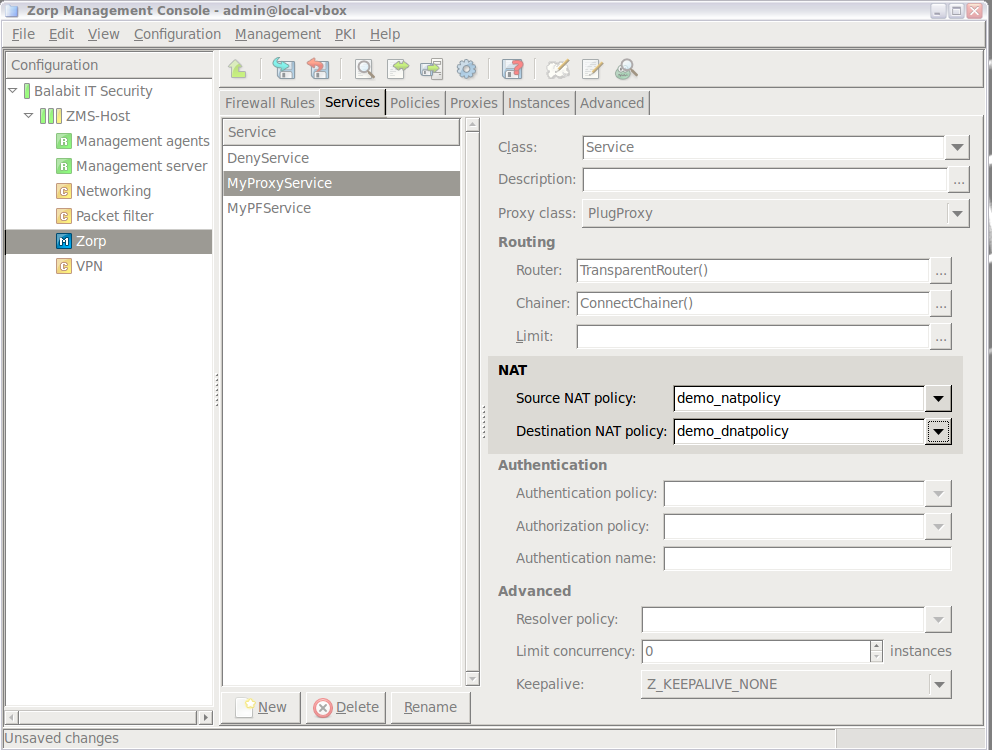
Remember that NAT policies are independent configuration entities and come into effect only if they are used in service definitions. Also, SNAT and DNAT policies are two different and independent service parameters: it is not required to have either one or both in any service definition. One service can only use a single NAT policy (or none) as its Source and another one (or none) as its Destination NAT policy parameter. These two settings usually do not reference the same NAT policy (although this is not impossible).
In general, while all NAT policies are equal in that they are freely usable as either source or destination NAT policies in service definitions, they are typically created with their future use in mind. There is no specification on whether NAT policies are SNAT or DNAT policies: they are SNAT or DNAT policies only from the point of view of the services that are using them.
NAT policies can be reused. Any number of services can use them.
| Note |
|---|
Although it is often considered a security-enhancing feature, NAT is not intended for access control of any type. Instead, use proper Zone setups and service definitions for this purpose. |
NAT in Application-level Gateway is an option to change source/destination IP address information in the server side of connections of the firewall, immediately before the connection is started. Since NAT (if used) decisions are made after all other IP address related configurations, such as router, proxy configuration, NAT can override these previous settings. NAT in Application-level Gateway can be used to shift IP address ranges, to set IP addresses and to customize these operations.
In a service definition there are potentially two different components that directly deal with IP address setting:
a router (compulsory),
and a NAT policy (or two) (optional).
In the address setting procedure the following processes are involved.
Incoming connection is accepted and a new session is created.
-
Destination address is set by the Router and using the option the source address of the server side connection is also set.
Remember that the Router only gives a suggestion for the source/destination IP addresses as the proxy or the NAT can later override these suggestions.
Router settings can be altered by the proxy if the option is set or
InbandRouteris selected and the proxy has some protocol based information.NAT is performed, depending on NAT types (SNAT/DNAT).
Access control check is performed based on the final destination IP address decision. Check whether the service is allowed as an
inbound serviceinto the zone where the destination IP address belongs to.The connection to the server is established.
| Note |
|---|
When checking the inbound services of the zone, the IP address to which the firewall actually connects to is considered. In other words, the original destination address of the client may be overridden by the router, the proxy and DNAT as well. Zone access control uses only the final IP address, all interim addresses (set by the Router, Proxy, but not used as the final one) are ignored in the access control decision. |
If a service uses an SNAT Policy, the is implicitly set as well so that SNAT uses the client IP address instead of the firewall IP address. That is, if the NAT policy does not include SNAT modification, the client's IP address is used even if the is unset in the router.
| Tip |
|---|
The versatility of NAT policies is especially useful in large-scale, enterprise deployments or where a lot of NAT is used. |
Resolver policies specify how a given service should resolve the domain names in client requests. This capability is essential when non-transparent services are used, as in these cases the PNS host has to determine the destination address, and the results of a name resolution are needed. Application-level Gateway is also able to store the addresses of often used domain names in a hash. Application-level Gateway supports DNS-based () and Hash table-based () name resolution.
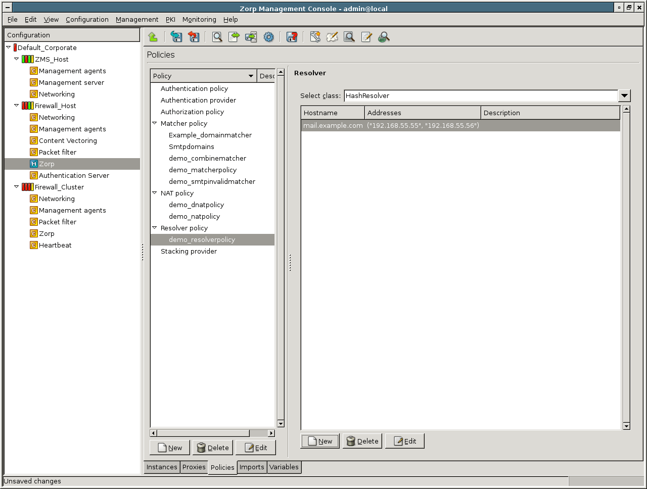
policies query the domain name server used by Application-level Gateway in general to resolve domain names. If a domain name is associated to multiple IP addresses (that is, it has more than one 'A' records), these records can be retrieved by checking the checkbox. (The DNS server used by the PNS host can be specified on the tab of the component, see Section 5.3, Managing client-side name resolution for details.)
| Tip |
|---|
Retrieving multiple 'A' records is useful when Application-level Gateway is used to perform load balancing. |
| Example 6.15. Defining a Resolver policy |
|---|
|
Python: Below is a simple DNSResolver policy enabled to return multiple 'A' records. ResolverPolicy(name="Mailservers", resolver=DNSResolver(multi=TRUE)) |
policies are used to locally store the IP addresses belonging to a domain name. A domain name () and one or more corresponding IP addresses () can be stored in a hash. If the domain name to be resolved is not included in the hash, the name resolution will fail. The HashResolver can be used to direct incoming connections to specific servers based on the target domain name.
| Example 6.16. Using HashResolver to direct traffic to specific servers |
|---|
|
If a PNS host is protecting a number of servers located in a DMZ, the connections can be easily directed to the proper server without a DNS query if the hostname – IP address pairs are stored in a HashResolver. If multiple IPs are associated with a hostname, simple fail-over functionality can be realized by using . The resolver policy below associates the IP addresses Python:
ResolverPolicy(name="DMZ", resolver=HashResolver(mapping={"mail.example.com":\
("192.168.1.12", "192.168.1.13")}))
|
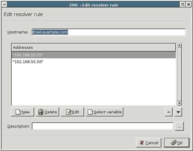
Stacking providers are external hosts managed by the Content Filtering (CF) performing various traffic analysis and filtering (for example, virus and spam filtering). These hosts can be listed as Stacking providers, and easily referenced from multiple service definitions.
A Stacking provider includes the IPv4 or unix socket of the host performing the analysis of the traffic. If multiple hosts are set in a single policy, they will be used in a fail-over fashion, that is, if the first host is down, the traffic will be directed to the second one for analysis, and so on.
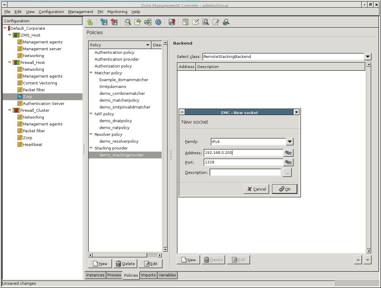
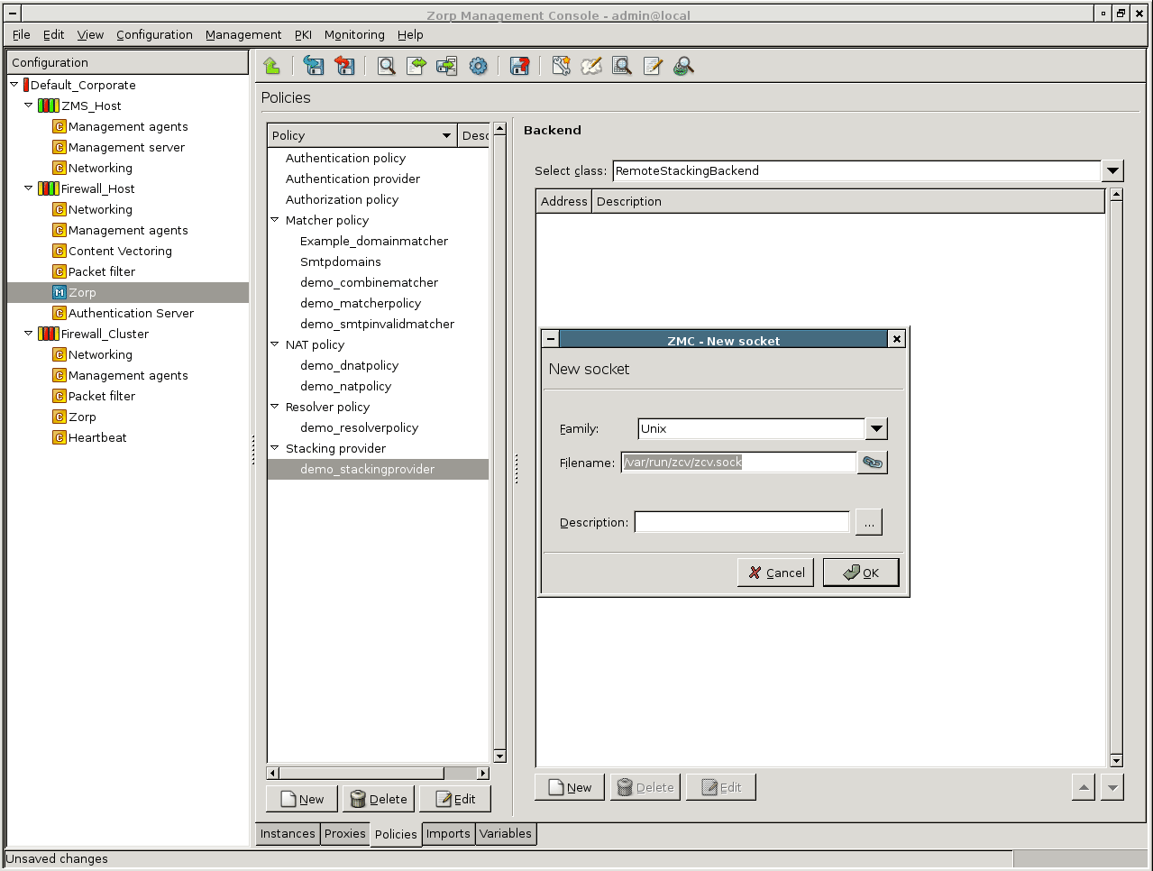
To specify an IPv4 socket, the IP address and port of the host has to be specified. To specify a unix domain socket, the full path (including the actual filename) has to be provided.
For details about CF and the configuration and use of stacking providers, see Chapter 14, Virus and content filtering using CF.
MC provides a status window to monitor the active connections of an instance (for information on instances, see Section 6.3, Application-level Gateway instances). Navigate to the MC component, select an instance, then click .
| Tip |
|---|
Multiple instances can also be selected. |
The window displays the following parameters of the active services within the instance:
: Name of the service (for example,
intra_HTTP_inter).: Name of the proxy (for example,
MyHttpProxy).: The proxy class from which the proxy module used in the service definition was derived (for example,
HttpProxy).: IP address of the client.
: Port number of the client.
: The IP address targeted by the client.
: The port targeted by the client.
: The zone the client belongs to.
: IP address of the server.
: Port number of the server.
: The IP address used by Application-level Gateway on the server-side (the server sees this address as client address).
: The port used by Application-level Gateway on the server-side (the server receives the connection from this port).
: The zone the server belongs to.
| Note |
|---|
The and parameters are empty for packet-filter services. |
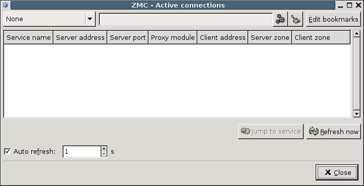
The list of active connections is not updated real-time, it is only a snapshot. It can be updated by clicking . The displays the configuration of the selected service on the tab.
The window is a Filter window, thus various simple and advanced filtering expressions can be used to display only the required information. For details on the use and capabilities of Filter windows, see Section 3.3.10, Filtering list entries.
PNS can automatically create daily, weekly, and monthly statistics about the transmitted traffic, and send them to an administrator or auditor through e-mail. The reports are in Adobe Portable Document (PDF) format. Note that these reports do not provide detailed statistics about every host on your network, rather they can be used to identify the most active hosts ("top-talkers") and to examine trends and sudden changes in the statistics (outliers).
In general, every section of the report consists of a table that details the ten most active clients (for example, the ten clients who transferred the most data in a zone) and a pie chart that displays every client. Note that on the pie chart, only the clients responsible for at least ten percent of the total value are labeled, all other clients are aggregated under the Others label.
| Note |
|---|
Every PNS host, and every node of a PNS cluster creates and sends a separate report. Reporting options must be configured on every PNS host separately. |
The reports include the following information:
: Traffic statistics for the entire network.
: Traffic statistics for every zone defined in PNS. Note that this report can be long if there are many zones defined.
: Statistics for the total transferred SMTP traffic, as well as for the most active accounts. Top senders and recipients are listed separately.
: Statistics about spam and infected e-mails.
: Statistics about connection-attempts that were blocked by PNS.
: List of websites generating more than a set amount of traffic, and a list of their top visitors. By default, ULR Reports are not included in the regular reports, see Procedure 6.9.1, Configuring PNS reporting for details on configuring them.
6.9.1. Procedure – Configuring PNS reporting
Login to the PNS host locally, or through SSH, and edit the
/etc/zorp/reports/options.conffile. Alternatively you add this file to the Text Editor plugin of MC (see Procedure 8.1.1, Configure services with the Text editor plugin for details).Enter the e-mail address where the reports should be sent into the
ADMINEMAILfield.Enter a name for the daily, weekly, and monthly report files into the
TITLE_DAILY, TITLE_WEEKLY, TITLE_MONTHLYfields.By default, the reports do not include statistics about visited websites. To include statistics about visited websites and the clients who visited them, enter a positive number into the
URLSfield. URLs that generate traffic higher than this value in megabytes will be included in the reports. For example,URLS=1024will include every website that generates at least 1 GB traffic. The direction of the traffic does not matter, uploads and downloads are added together.Save the file.
| Warning |
|---|
The reports are only sent to the e-mail address set in |
| Tip |
|---|
To generate reports manually for arbitrary time periods, use the report.py command-line tool. Run report.py without parameters to display the available options and parameters of the application. |
Firewall design and implementation generally require the presence of a subsystem that is responsible for accountability. This subsystem stores information on user and administrator activities performed on or through the firewall and must be configurable to provide exactly the amount and type of information needed which, on the other hand, is usually defined by the corporate IT Security policy.
This requirement in computer systems is typically fulfilled by a logging subsystem. Logging is the act of collecting information about events in the system. The result of logging can be the following.
one or more log files (binary or text-based files)
the console
rows in a database table if logging is set up to use a database as the output store
These log files are archived for event–tracking purposes. Apart from a simple, automated archiving procedure, however, these log files must be continuously analyzed. Logging records user and system activities in (quasi) real-time, so a continuous analysis is capable of detecting malicious user activities or system malfunctions as they happen, thereby allowing for an effective and quick response policy.
In security-sensible systems, such as the PNS firewall, logging must be a system–wide action, that is, all the relevant components of the system provide logging information, or log entries. Then, there must also be a central component, a logging subsystem, that collects log entries from the various system components and organizes them into a log file of some format (the term file is used literally here and does not necessarily mean a text or binary file: it is simply the output of logging that can be a database, the console or some input queue on another machine). It would not be practical nor economical for all the components to manage their own log files. It would waste system resources (more open file handles, database connections or network sessions, depending on the output destination used) and would make analysis cumbersome (hunting for information in several separate log files that would probably be syntactically incompatible).
In PNS, centralization is elevated to a higher level: the logs of the central logging subsystem on all machines are unified on a network–wide dedicated central logging machine. This way log analysis, reporting and archiving is simpler even for larger networks with many entities providing logging capabilities.
These requirements have, in part, long been targeted by the Unix syslog subsystem. For decades, syslog was the ultimate central logging subsystem for Unix and Linux machines. It is an old and rather unreliable technology and lacks some flexibility and security features that are required in today's demanding network and security environments. Therefore, a replacement service called syslog-ng, where "ng" stands for "next generation", has been created. The syslog-ng application inherited all the concepts, features and most of the naming conventions from syslog and enhanced it with several new features targeting flexibility and security requirements. PNS uses syslog-ng as its logging subsystem.
The following sections include a short introduction to the concepts of syslog-ng, and describe how MS works with syslog-ng and how this subsystem can be managed with MC.
The syslog-ng application runs as a daemon process and collects information from various log sources. Depending on the options and filters configured, syslog-ng saves the received log entries to the specified destinations. The configuration of syslog-ng mainly consists of configuring its components correctly.
The components of syslog-ng are the following:
Sources
Options
Filters
Destinations
The syslog-ng configuration is stored in a text-based configuration file that is typically the /etc/syslog-ng/syslog-ng.conf file. MC hides the exact structure of this configuration file and takes care of the correct syntax, allowing you to concentrate on the actual configuration tasks. Still, because syslog-ng is present in ever more Linux/Unix distributions, it can be beneficial to know the syntax and contents of this configuration file too. In addition, syslog-ng allows for centralized logging from machines not necessarily under the control of MS. In this case configuring syslog-ng means manually editing the corresponding configuration file.
The syslog-ng.conf file has a C-like syntax with curly braces ({}) separating integral code parts and with semicolons (;) for closing expressions. Comments begin with hashmark (#).
It is possible to provide syslog-ng with global options that affect all the logging commands, although they can be overridden, if required. For further details, see Section 7.2.2.3, Configuring destinations.
There are several different options available, some of them especially useful when dealing with log entries coming from other machines on the network. By default, these entries are recorded using the sender host's IP address, but using options use-fqdn(), use-dns(), chain-hostnames() and keep-hostname() it is also possible to look up hostnames for servers generating log entries.
For a full list of the available options and their descriptions, see Appendix C, Further readings.
There are several system components that do not output log entries in a unified format or method. Some of them output to files, while others use a pipe, or use a unix-stream. Some can even be configured to use a certain output method. The syslog-ng application can accept log entries from these output methods too.
The syslog-ng application supports the following source types:
-
internal()The log messages of syslog-ng itself.
-
file()This source is for log entries from a special file, like
/proc/kmsg.Note A file source cannot be an ordinary text file, for example, one generated by httpd. However, it is possible to feed syslog-ng with messages from such a file indirectly. For this, a custom script is required, for example, a script that uses tail -f to transfer messages from the desired logfile to the logger utility.
-
pipe()This source is for messages from a pipe.
-
unix_stream()This source is for log entries from a connection–oriented socket.
-
unix_dgram()This source is for log entries from connectionless sockets.
-
tcp()Log entries from remote machines that use TCP for log entry submission.
Note One of the advantages of syslog-ng over traditional syslog is that it can handle TCP connections.
By default, syslog-ng uses TCP port
514. -
udp()Log entries for remote machines that use udp for log entry submission.
By default, syslog-ng uses UDP port
514.
Of all the possible sources unix_stream() and unix_dgram() are probably the most important when dealing with local components' log entries because the most important system components, like the kernel and many of the daemon processes use one of them for recording log events.
The syslog-ng application can send log messages to the following types of destinations.
-
file()This destination is an ordinary text file. It is possible to use macros in filenames, thus you can create dynamic file names.
-
pipe()This destination is a named pipe.
-
program()This destination means the standard input of a given program.
-
syslog()Send messages to a remote syslog server specified by its IP address or FQDN using the RFC 5424 (IETF syslog) protocol over TLS, TCP, or UDP. The default destination port is
514. -
tcp()Send messages to a remote syslog server specified by its IP address or FQDN using the RFC 3146 (BSD syslog or legacy-syslog) protocol over TCP or TLS. The default destination port is
601. -
udp()Send messages to a remote syslog server specified by its IP address or FQDN using the RFC 3146 (BSD syslog or legacy-syslog) protocol over UDP. The default destination port is
514. -
unix_dgram()This destination is a connectionless Unix socket destination.
-
unix_stream()This destination specifies a connection–oriented Unix socket as a destination for log entries, for example,
/dev/log. -
usertty()This destination sends log messages to the terminal of a given user. Username is given as a parameter of usertty.
To fine-tune what log entries are needed or how they are forwarded to different destinations, it is possible to use filters in syslog-ng configurations. Although their use is optional, they are highly recommended because they represent the real flexibility of syslog-ng.
Filtering can be set using seven different criteria that are summarized in the following list.
- facility()
The type of messages referring to the nature of the log entry. For example,
auth,cron,daemon,kern,mail.- priority()
-
The assigned priority level of the log message.
The possible priority levels are the following in order of severity:
none,debug,info,notice,warning,err,crit,alert,emerg. - level()
The same as priority.
- program()
The name of the software component that generated the log entry.
- host()
The machine that the log message arrived from.
- match()
A regular expression that is compared to the contents of the log message
- filter()
Additional filter.
By combining these elements you can manually configure a fairly complex logging environment in a couple of lines of “code”, with basic knowledge on the syntax of syslog-ng rules. If you use MC, MC takes care of the correct syntax and allows you to focus on the actual rule creation process.
For more detailed information on syslog-ng, see Appendix C, Further readings.
7.2.1. Procedure – Configure syslog-ng
To configure system logging in Proxedo Network Security Suite complete the following steps.
Select the host where you want to configure system logging, then click .
-
Choose a template for the component.
The following templates are available for the component:
: Collects logs from
/dev/logand/proc/kmsg, and stores them in the/var/log/messagesfile.: Type the IP address of your logserver into the field. Collects logs from
/dev/logand/proc/kmsg, and stores them in the/var/log/messagesfile. The log messages are also sent to the logserver over TCP using the legacy BSD-syslog protocol (RFC3164).: Collects logs from
/dev/logand/proc/kmsg, and stores them in several different files, like the default syslog configuration on Debian systems.: Empty configuration.
-
View this initial configuration file by selecting the system logging component of a given host and click the button.

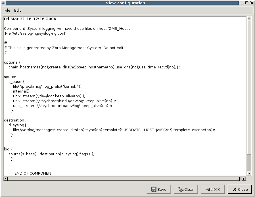
The main configuration window of the system logging component consists of five tabs, corresponding to the five main components of a syslog-ng configuration.
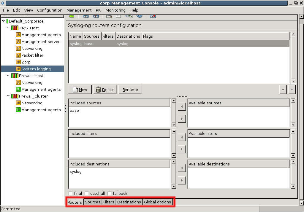
The only tab that needs some explanation is the first one, . This tab is used to assemble the actual log commands from the other components, so a router actually represents a log command entry in the syslog-ng.conf file. Therefore, during a configuration cycle, you are recommended to visit and configure the tab last. First, configure the tab to set up system-wide defaults, then you can continue with the and tab.
7.2.2.1.1. Procedure – Set global options
-
Configure parameters for I/O operation optimization.
File I/O is always expensive in terms of system time needed, so theoretically the number of (log) write operations should be minimized, keeping a number of incoming log entries in a memory buffer and batch-write them out to disk.
Note This buffer and thus the time between successive log write-outs cannot be too long because in case a hardware malfunction occurs and the machine has to be rebooted, the log messages that have not been written out yet are lost.
Time-related parameters are given in seconds. Message size is in bytes, while message queue size is an item number.
-
Set system time usage.
Macro substitution is possible in syslog-ng, for example when creating filenames. If you use system time as a macro variable, the default is to use local system time on the syslog-ng server that processes the log entries. If, instead, you want to use time values received in the log messages themselves, check the checkbox.
-
Configure file creation.
If you configure file creation to use many different directories that do not yet exist, the checkbox can be used to create them as needed.
-
Configure the required parameters.
The list of other configurable parameters in this tab includes the following.
- Message size
Defining the allowed maximum size for log messages.
- Message queue size
Defining the allowed number of messages waiting to be processed.
- Stats interval
Setting the syslog-ng's internal reporting interval. The syslog-ng application reports a number of parameters on its own operations and statistics.
- Mark interval
Setting the regularity of marking timestamps by the syslog daemon.
- Sync interval
-
Defining how often log messages are written out from memory.
The default '0' means there is no time delay, messages are written out continuously.
- File inactivity timeout
Defining after how long non-usage time the log files are closed.
- Reopen interval
Setting how often a log file can be opened again.
-
Assign owner and permission parameters to log files and directories created by syslog-ng.
By default, syslog-ng runs as root, but can be configured to run as a limited user as well. In this case you have to set the appropriate permissions, or use the defaults.
-
Set name resolution for syslog-ng.
Machine identification in log entries is accomplished using IP addresses. If you want to use hostnames that are easier to remember and recognize, you can instruct syslog-ng to perform name resolution. This name resolution only works for resolving the IP addresses of hosts sending log entries.
If there are IP addresses within the log messages themselves they are not resolved this way. To perform name resolution for those addresses, a log analyzer utility is needed. Name resolution is a time-consuming process and to achieve the best results, use a DNS server that is “close” to the syslog-ng server in terms of response time.
On the other hand, log entries are typically coming from a limited number of machines (servers) and their IP addresses tend not to change. Therefore, it is reasonable for the syslog-ng server to cache their resolved names locally, thus easing the heavy reliance on a DNS server.
You can configure DNS caching as a global option. The time values are in seconds, cache size is in bytes. File options can be changed in individual file destination configurations, but name resolution options cannot, they are always global.
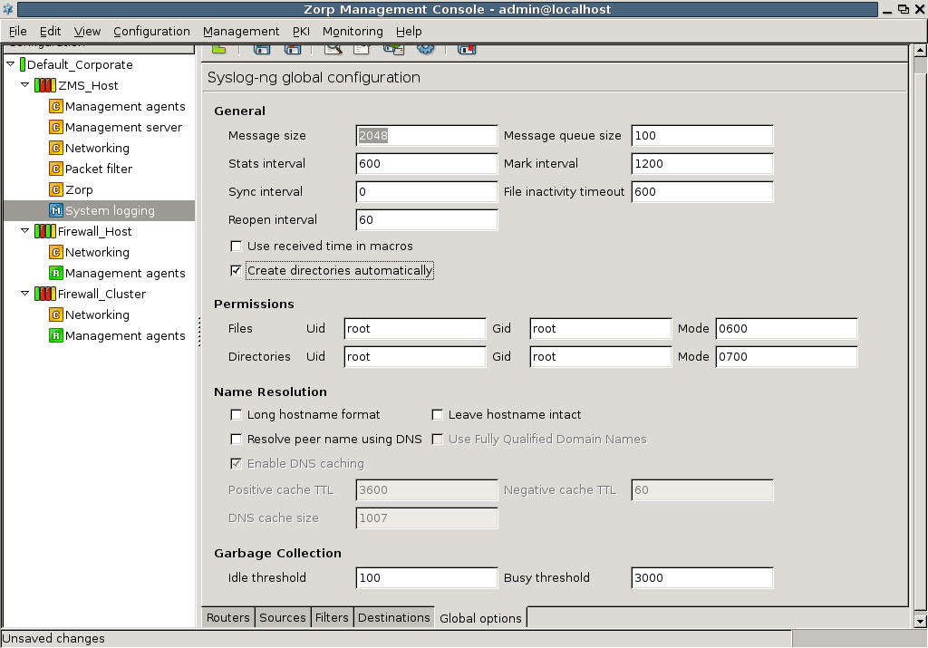
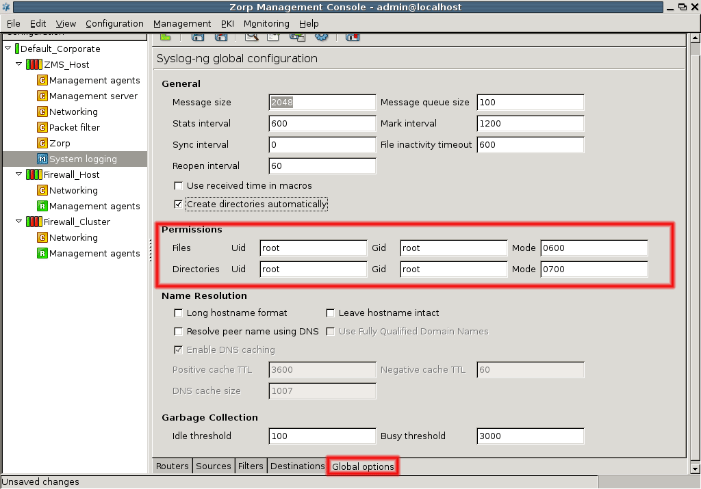
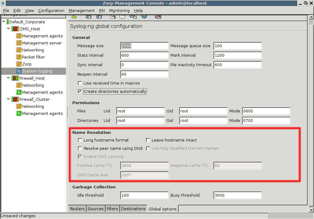
Sources are collections of communication channels where log entries can arrive. A source in syslog-ng can consist of one or more drivers. Driver is the actual communication channel that must be monitored for log messages.
By default, using one of the default templates, there is an internal driver for syslog-ng's own log messages, and there are three unix-stream drivers for /dev/log, bind, and ntp, respectively.
The default source is called base. To configure new drivers, either define them under this default source or create new sources. A source must always contain at least one driver.
7.2.2.2.2. Procedure – Create drivers
-
Click on the subwindow on the tab in
System loggingcomponent.The following window appears.
-
Select a driver type.
The rest of the options are based on this selection.
-
For unix_dgram, unix_stream, sun_stream and file driver types, set the filename.
Note None of these driver types are ordinary text files. File is a binary file while the others are socket endpoints, actually. Nevertheless, they are identified by filenames.
If you have a custom system component, for example, a daemon, that sends its log messages to a special socket and you want syslog-ng to collect this component's log messages, set up a driver for it. Many of the Linux daemons and other software components prefer
/dev/logbut it is not a central requirement. Some software can even be told through its configuration file where to log.-
For TCP and UDP source drivers, specify an IP address and a port number.
The machine running syslog-ng waits for log messages from other servers on this IP address/port pair. In other words, here you do not specify where, that is, what machines, log entries arrive from, but on what IP address/port pair syslog-ng collects these log entries.
The default port for both TCP and UDP is 514.
For TCP drivers some additional parameters can be supplied.
Since TCP is a connection–oriented protocol, a virtual session is always established between the communicating parties. This session buildup takes time and bandwidth (three-way handshake), so to save on these resources, if a session is built between syslog-ng and the host sending log entries, it is kept alive with the help of . However, if the number of active TCP sessions is high, it can have negative effect on the performance of the host running syslog-ng. On the other hand, if the number of sessions is kept low, using the setting, some log messages may be lost if the connection limit has already been reached.
Another small optimization setting is the checkbox: it instructs the system not to close open TCP sessions while syslog-ng configuration is reloaded.
These two settings are available for the unix_stream driver type as well.
-
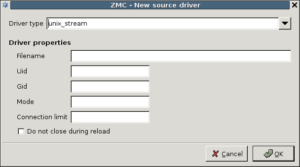
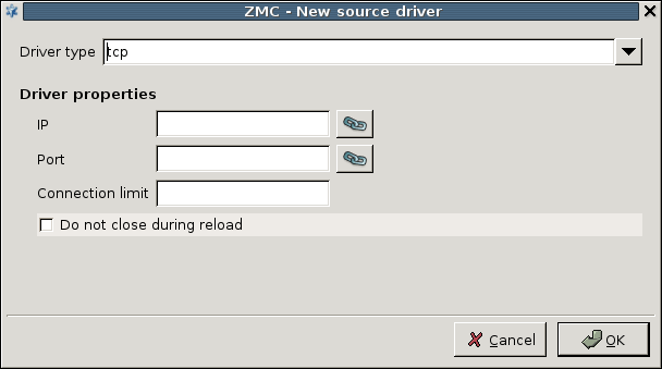
The logic behind destination configuration is the same as with sources configuration. You can create one or more destination directives and fill them with drivers specifying the actual channels on which log messages are recorded.
The available destinations are the following.
File
syslog: TCP, UDP, or TLS-encrypted TCP through the RFC5424 (IETF-syslog) protocol,
TCP through the RFC3164 (BSD-syslog or legacy-syslog) protocol, including TLS-encrypted TCP
UDP through the RFC3164 (BSD-syslog or legacy-syslog) protocol
Pipe
-
Program
Program specifies the input of a software, typically a script, that can perform an action based on the input log message it receives.
Tip This may be a good solution to set up an alerting mechanism.
Unix_dgram
Unix_stream
-
Usertty
Usertty is a terminal to which log messages can be displayed; it is meaningful as a destination if there is someone actually monitoring that terminal, or the named terminal is routed to some other, special destination.
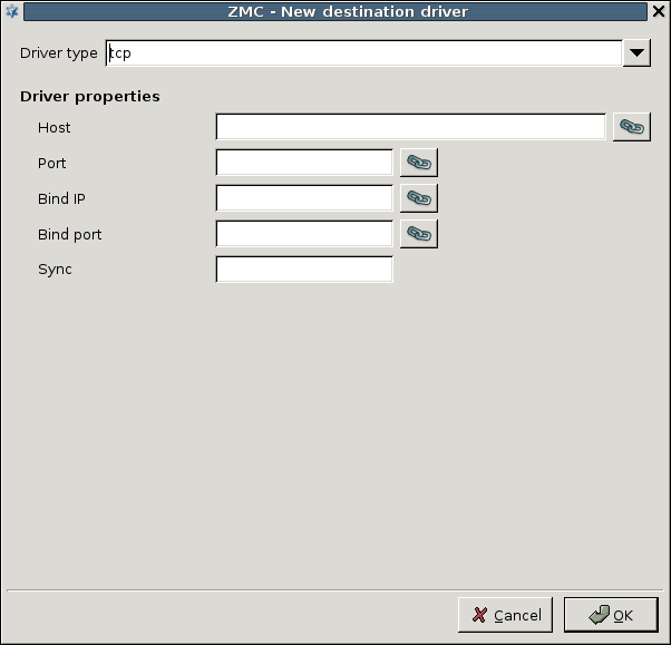
and define the destination of log messages on the network, while and specify where (in which direction) the log messages are sent out from the host. This is especially important for firewalls which almost always have two or more interfaces and a number of IP addresses.
File destination also has some important properties that need some explanation:
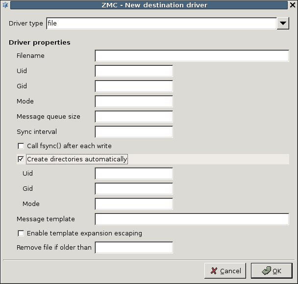
Most properties are present also on the tab: many of the global options can be overridden in file destination setup. For the descriptions of the properties, see section Section 7.1.1, Global options.
A special property is the . This property can be used to apply some basic formatting on log messages: according to the example given on Figure 7.11, Macro substitution in file naming, all log messages that end up in /var/log/syslog have a timestamp ($ISODATE) and a hostname ($HOST) inserted before the actual log message ($MSG). This is the default behavior in PNS.
| Note |
|---|
The property is not to be confused with macro substitution in filename creation. Message templates can format actual log messages, while macro substitution can format log file names. |
For example, if you want to create a new logfile every day, modify the filename property on Figure 7.11, Macro substitution in file naming the following way.
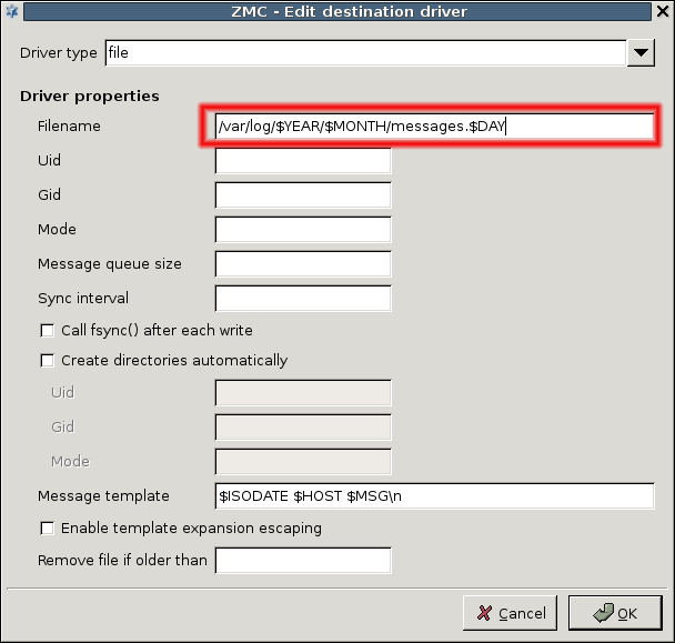
An optional component of syslog-ng configuration is filter creation. Filters can be used to pick log entries from defined sources with the possible intent of sending selected log entries to different destinations.
| Example 7.1. Selecting log messages from Postfix using filter |
|---|
|
The following is a trivial filter to select log messages coming from Postfix: filter f_postfix{program(“postfix”);}; |
Filters can use regular expressions in a match criteria and a number of other criteria as well. For a complete list of criteria, see Section 7.1.4, Filters. Due to the flexible nature of filters, it is almost impossible to create a usable GUI to interface them. Therefore, the tab of the System logging component is quite simple.
7.2.2.4.1. Procedure – Set filters
-
Create one or more filters.
See Section 7.2.2.2, Configuring sources and Section 7.2.2.3, Configuring destinations.
-
Set up a rule for each filter in the textbox.
MC aids in filter creation by taking care of the necessary curly braces ({}) and semicolons (;).
So to create a syntactically correct postfix filter, only enter the filter rule textbox the following part:
program(“postfix”)
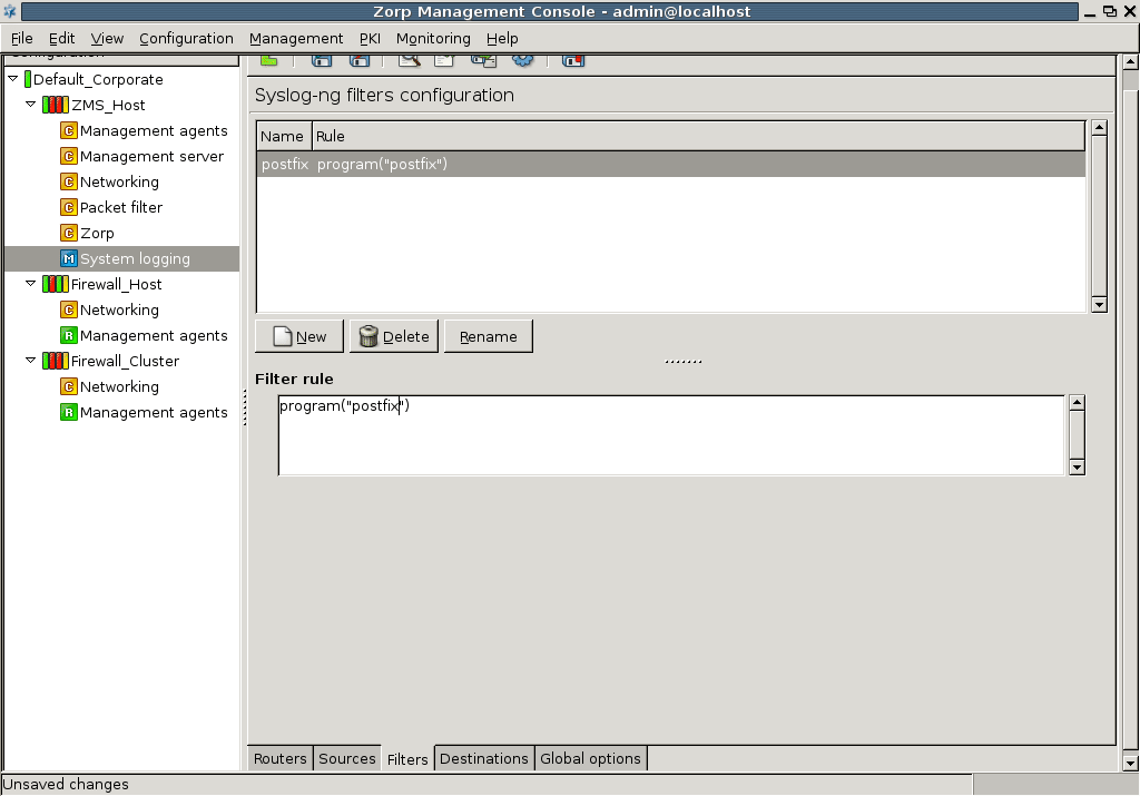
For further information on possible filters, see Appendix C, Further readings.
Logging rules are called Routers in syslog-ng terminology. Rules consist of a source, optionally a filter and a destination. The tab of the System logging component represents this philosophy well.
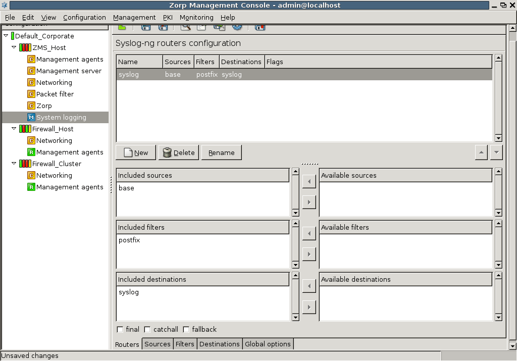
Just like sources, destinations and filters, more than one router can be present in the system. If you use several routers, you are recommended to apply a good naming strategy to easily identify your log rules.
7.2.2.5.1. Procedure – Configure routers
To create a router click on .
Provide a name for the new router.
-
Select the components from the list of available sources, filters and destinations.
Example 7.2. Setting up a router If you select
baseas the source,postfixas the filter (optional, use the small arrow between the text boxes) andsyslogas the destination, the resulting router, that is, the log rule looks like this:log { source(s_base); filter(f_postfix); destination (d_syslog);flags ( ); };
-
Specify flags for the router.
The flags component is empty. Use the checkboxes at the bottom to select the flag. Three possible flags are available.
-
Final flag, meaning that the processing of log statements ends at this point.
Note Ending the processing of log statements does not necessarily mean that matching messages are stored once, as there can be matching log statements processed prior to the current one.
Fallback flag, making a log statement 'fallback'. Being a fallback statement means that only those messages that do not match any 'non-fallback' log statements are sent.
Catchall flag, meaning that the source of the message is ignored, only the filters are taken into account when matching messages.
-
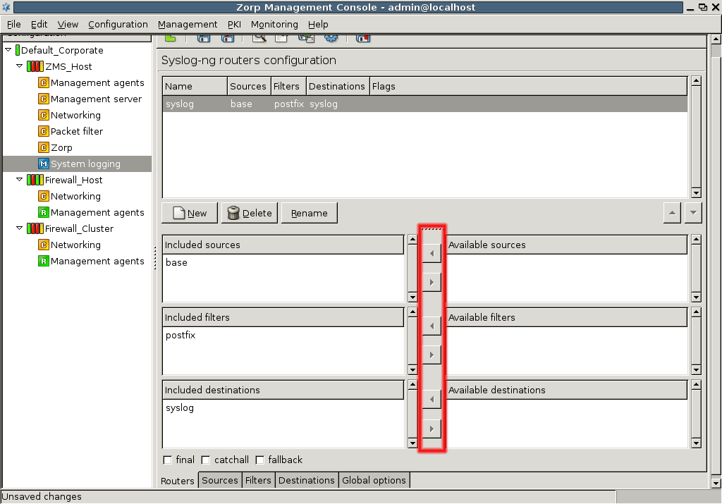
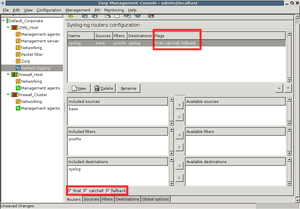
There are virtually endless possibilities for configuring a complex system logging architecture with syslog-ng. This chapter focused only on the basics and provided an architecture that not only means PNS and MS host nodes, but syslog-ng architecture can also include practically any favor of Unix/Linux machines.
For further information and details, see The syslog-ng Administrator Guide
7.2.3. Procedure – Configuring TLS-encrypted logging
Purpose:
To encrypt the communication between the PNS host and your central syslog server, complete the following steps.
Steps:
-
Navigate to , and enter a name for the new destination (for example,
tls-logserver). Select , then .
-
Set the hostname and port of your logserver in the and fields.
Select the network interface of PNS that faces the logserver from the field.
Select .
If your logserver requires mutual authentication, that is, it checks the certificates of the log clients, select the certificate PNS should show to the logserver from the field.
Select the trusted CA group that contains the certificate of the CA that signed the certificate of the logserver from the field.
By default, PNS will verify the certificate of the logserver, and accept only a valid certificate. If you do not need such strict check, modify the option. For details on the possible values, see Section 3.2.5, Certificate verification options in Proxedo Network Security Suite 1.0 Reference Guide.
Click .
-
Select , and add this new destination to a router.
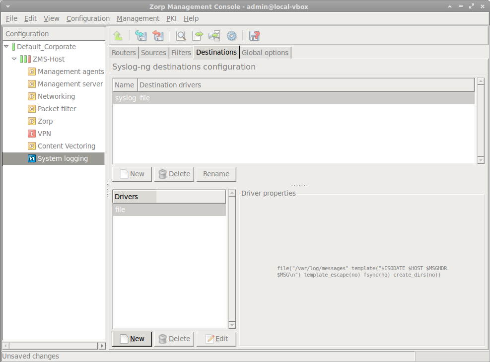
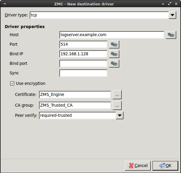
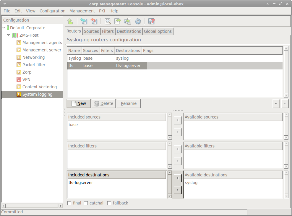
All the essential parts of PNS configuration have a corresponding custom configuration component in MC. For custom, auxiliary services that are not part of the default PNS configuration but installed separately, for example, a Snort Intrusion Detection System (IDS) service, MC provides a generic tool, the Text editor plugin configuration component to edit text-based configuration files. Since practically all Unix services work with text-based configuration files, the plugin can be used to configure all of them remotely.
Although the Text editor plugin provides only a simple text editor functionality, if you use this tool to configure the custom services, they are placed under the control of MS. From MC, the configuration changes are first committed to the MS server and stored there. After an upload command, these configurations are handled by the zms-transfer-agent on the corresponding PNS firewall. So any service installed on the PNS host are, in effect, MS-managed.
The number of plugins is not limited, you can add as many of them as needed. Furthermore, a single plugin can be used to edit more than a single text file.
The Text editor plugin in MC is called Text Editor. It can be added to the list of configuration components the usual way.
8.1.1. Procedure – Configure services with the Text editor plugin
-
Select a configuration template.
By default, there are some predefined configuration templates available, these are actually configuration file skeletons for the given services.
Unless you want to configure DNS or NTP services, select Text editor minimal template.
The following configuration window appears.
-
Supply Text component name.
This parameters sets a label for the component.
-
Give Component configuration file name.
Component configuration file name refers to the actual configuration file on the host that you want to edit.
It is most likely a file in
/etcor in one of its subdirectories since this is the default location for configuration files. -
Set Component init script.
Component init script refers to the script file or a link to it that is used to start and stop a given service. Without providing this file you cannot start/stop the service from MC. These scripts are installed in
/etc/init.d.Note MC automatically prepends the
/etc/init.dprefix, just type the name of the script. -
Click after setting the necessary parameters.
The main window of MC reappears with an empty component pane. This is normal; before working with the desired configuration file it is possible to download the content from the selected host.
-
Download and edit content from the selected host.
Use the following button in the button bar to download the file to MC:

You can edit the configuration file.
-
Propagate the modifications to the firewall.
The steps are identical to that of the other components: commit the edited file to MS and then upload it to the host. Finally, the service can be started/stopped/restarted or reloaded the usual way.
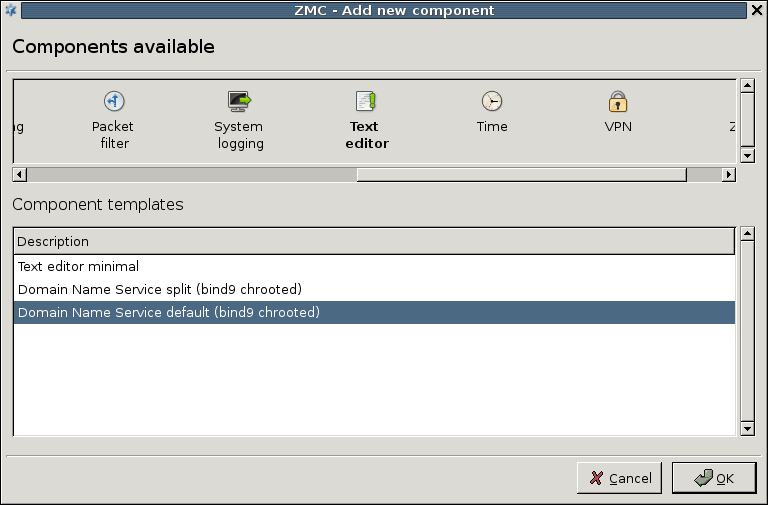
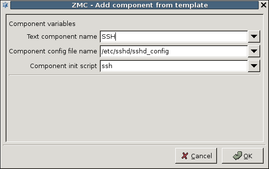
Besides the file download option, the Text editor plugin provides some unique features compared to the other components.
8.1.2. Procedure – Use the additional features of Text editor plugin
-
To simplify working with configuration files, you can insert pre-created configuration file segments with the help of the
 button on the button bar.
Note The file to be inserted must be present on the MC machine. If you insert more than one files, they appear concatenated in the main workspace.
-
You can create new files with the button on the button bar.
If you create more than one file, they appear on different tabs in the main workspace of the plugin. This way a single plugin can host several different files.
Note If you create a file with the Text Editor component, MC sets the permissions of the file and the directory to
root:root 700, regardless of the original permissions or the umask settings of the system. -
You can remove configuration files with the button.
By default, the button only removes the configuration file from the MS database. If you want to remove the file from the host as well, check the appropriate checkbox in the dialog box.
-
You can also place links to linkable objects of the configuration in a file, if you right-click in the main workspace of the plugin and select the local menu.
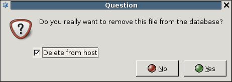
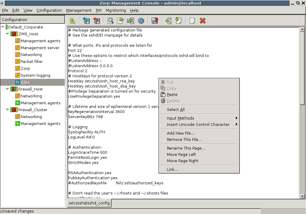
| Note |
|---|
There is no restriction on what file can be administered via the plugin except that it must be a text-based file. |
The default PNS installation includes some service components that are typically useful in networking environments. These are BIND for DNS traffic, NTP, and Postfix for SMTP traffic. The use of these services is not mandatory, however, they can help solving three particularly problematic issues of network configuration. Once configured, access to these services (so called local services), as well as remote SSH access to the PNS host must be enabled separately by adding a local service. See Section 9.4, Local services on PNS for details.
For enhanced security, some of these services run in a chrooted environment, otherwise known as a jail. A jail is a special, limited directory structure where the service executables and all the accompanying files, such as configuration files, are installed. The service that is jailed can only access this limited part of the file system hierarchy and is unaware of the rest of the file system. The 'chrooted environment' is a virtual subtree of the full file system, and the top of this subtree is seen by the chrooted (jailed) service as the root '/' directory. From the service's point of view, the jail is a complete file system in the sense that it contains all directories the service needs access to. For example, if the service needs a library from /lib or from /usr/lib, these two directories together with the actual lib files needed are included (copied) in the jail environment. The jail isolates the service from the rest of the system, so even if its security is compromised, it can only destruct the jail and cannot affect the rest of the system.
| Note |
|---|
Starting with PNS 3.4, the BIND and NTP services do not run in jail, but use AppArmor instead. It is possible to set the BIND service to run in jail automatically. |
BIND is the industry standard DNS solution used in the vast majority of Linux/Unix based name resolution services. It has three different “branches”, ISC BIND 4, 8 and 9, the most advanced development taking place in the ISC BIND 9 branch.
Installing PNS automatically installs an ISC BIND 9 version. BIND shipped with PNS is a full implementation of the most up-to-date version of the 9 branch, so theoretically it is possible to configure it for any DNS server role. It is hosted on a firewall, however, such liberal use of BIND is not recommended. Instead, it should rather be used as a limited-purpose DNS server. The following two examples are such possible configurations.
| Example 9.1. Forward-only DNS server |
|---|
|
In this scenario, BIND does not store zone information of any kind, instead, it simply forwards all name resolution requests to a designated nameserver located elsewhere. This way, BIND configuration and maintenance is minimal while name resolution traffic is optimized: BIND caches resolved name-to-IP address mappings, thereby saving some bandwidth and improving name resolution speed. This setup is especially recommended for small to medium-sized networks where DNS zone information of the company is maintained off-site, typically at an ISP, and thus maintaining a dedicated nameserver only for Internet name resolution is not economical. In this setup BIND operates essentially as a DNS proxy. |
| Example 9.2. Split-DNS implementation |
|---|
|
In this setup two sets of records on the DNS server are maintained:
With this setup it is possible for the company to both maintain its own public DNS zone records (SOA, NS, MX and A records for hosts running popular services like WWW or FTP) and some internal DNS records for servers that are (and must be) available for internal users only. This setup is recommended for companies wishing to host their own DNS zone database but the number of external name resolution requests does not facilitate the use of a dedicated DNS server. |
The configuration of BIND is stored under /etc/bind/, where the most important file is named.conf. This is the general configuration file. Zone database information is stored in db.domainname files under the same directory.
MC does not offer a dedicated component to edit BIND configuration, instead, the Text editor component offers preconfigured templates for this task.
9.1.2.1. Procedure – Configuring BIND with MC
Add the
Text editoras a new component.-
Select a template to be used with the Text Editor.
Select one of the first two templates depending on whether your want a split DNS configuration or not.
Click .
-
Configure the basic settings in the opening window.
-
Provide name.
This parameter simply specifies a label for the component that appears in the components pane.
-
Specify .
This parameter defines where the outgoing name resolution requests originate on the firewall.
Note Prior to BIND 8.1 the source port was 53 (just like the destination port), but since then BIND uses a port from the dynamic range, 5300 by default.
This might be important in back-to-back firewall configurations where there is another firewall in front of this instance of PNS. To allow outgoing DNS requests, the front firewall must know the source port used by the BIND service.
Besides supplying an alternate port number, you can supply a fixed IP address of PNS if it has more than one in the required direction. If this setting is not relevant in your network environment, choose the IP address of the outside interface.
-
Define .
In a PNS installation, BIND is usually configured as a forward-only nameserver. If you configure a forwarder, BIND does not resolve names recursively on the Internet, but instead it forwards all name resolution requests to the DNS server specified as the forwarder.
After entering values for these parameters the first round of BIND configuration is ready, a functional forward-only nameserver is in place.
-
-
To permit access to the BIND service, enable the
dnslocal service. If you plan to host zone database information on the PNS Gateway, enable thedns-zonetranslocal service as well. See Section 9.4, Local services on PNS for details.Note If you use zone transfer, be careful with selecting which zones you accept zone transfer requests from.
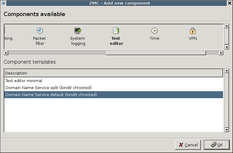
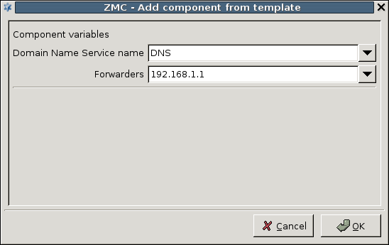
If you go back to the DNS configuration component you can see the structure of the named.conf file with the values entered for query-source and forwarders.
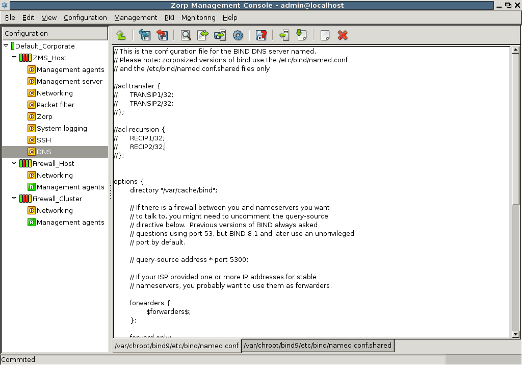
In addition, this tool is suitable for editing the named.conf file only. If you want to host zone database files ( db.domainname) on the firewall, you can edit the files separately if you create a new file in the Text Editor component. However, for forward–only nameserver configurations editing the named.conf file is generally sufficient.
9.1.3. Procedure – Setting up split-DNS configuration
Setting up a split DNS service is useful in networks where both external and internal name resolution is performed using the same DNS server – in this case the PNS firewall. Since hiding the internal namespace from external visitors is a basic security requirement, you have to set up the DNS service in a way that it does not resolve internal names for external resolvers. In other words, for all DNS zones stored on the server you have to specify which networks can query for records in the given zone.
Add the Text Editor component.
-
Select the template.
Two skeleton files are created, a
named.confand anamed.conf.shared.The
named.conf.sharedfile holds records and configuration settings that are shared between external and internal name resolution operations, whilenamed.confhas options to specify internal and external networks (internalipsandexternalips). These networks can then be referenced indb.domainnamefile(s) to specify which networks can have access to what records.For more information on split-dns configuration and DNS configuration in general, see Appendix C, Further readings.
Accurate timekeeping is very important for firewalls. Without reliable time data, security log analysis is very difficult and can lead to false results. Besides, if the firewall provides any auxiliary services that use timestamping, for example, a mail service, false time values can be disturbing, too. One of the few things that are still operating in the original, free and liberal spirit of the Internet is the Network Time Protocol service. There are a number of timeservers on the Internet that allow free connections from anywhere. For a complete list, see Appendix C, Further readings.
Companies typically connect to a Stratus 2–level timeserver on the Internet and then distribute time within their organization from a single time server source. Using the native NTP service PNS can function as a central timeserver for the entire organization, if needed. This service generally does not put a heavy load on the machine, nor does it pose a significant security risk, so it is generally acceptable to use PNS as a timeserver for the internal machines.
Unlike application proxy plugins, native services operate as feature–complete software components, so the NTP component in PNS is a real NTP server. NTP is generally not suitable for proxying, since the latency of the proxy component would not be constant but load–dependent rather. Packet filtering could work for NTP but application–level handling of traffic generally offers a higher level of security. NTP is handled by a native service based on these reasons.
9.2.1. Procedure – Configuring NTP with MC
NTP has a separate configuration component in MC.
-
Add the
Timecomponent to the PNS host in MC. It is recommended to select theDate and time chrootedtemplate. Name the component.
-
Specify a time server with which PNS synchronizes its system time.
-
Configure the subcomponents. Date and time can be updated from the specified time server by clicking , or set manually.
-
Set date and time information manually, using the three-dotted (...) button.
If you click the buttons, a dialog box warns you that instead of setting date and time information manually, you should force an update from the configured timeserver with the ntpdate command. To synchronize the time to the time server, click the button in the bottom of the window.
You are recommended to use ntpdate instead of manually tuning date and time values because the Internet time is probably more accurate than other, local time sources.
If you want to permit your clients to synchronize their clocks to the PNS host, enable the
ntplocal service. See Section 9.4, Local services on PNS for details.-
List the NTP servers PNS can communicate with.
For time synchronization fault tolerance, you are recommended to add at least two servers to the list. Click and enter the address of the NTP server, as well as the interval when the clock of the PNS host should be synchronized to the NTP server.
-
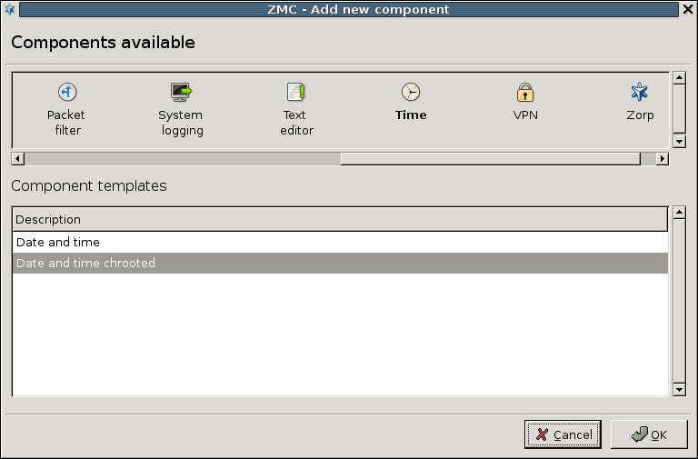
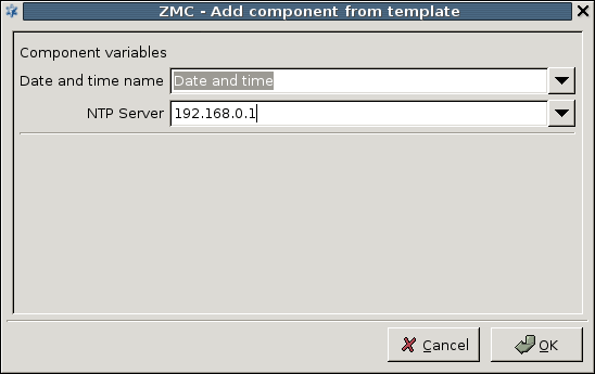
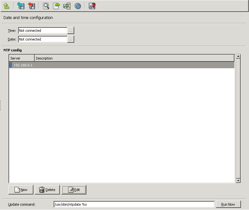
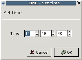
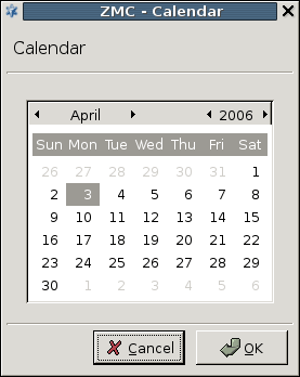
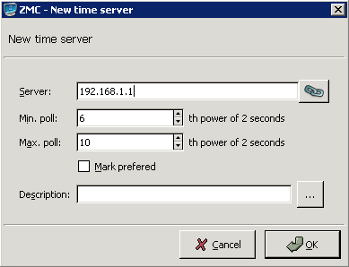
The status of the configured time servers is indicated by leds of different colors before the name of the server. Hovering the mouse over a server displays the following statistics about the connection in a tooltip (for details on these values see Appendix C, Further readings):
Tally code:
Ref. ID: The reference ID (0.0.0.0 if unknown).
Stratum: Place of the server in the 'clock strata' hierarchy. Stratum 1 systems are synchronised to an accurate external clock; stratum 2 systems derive their time from one or more stratum 1 systems, and so on.
Type: The type of the peer (local, unicast, multicast or broadcast).
Last arrived: The time when the last packet was received.
Polling interval: The period between two queries in seconds.
Reachablility: Register indicating the reachability of the peer. A peer is considered reachable if at least one bit in this register is set to one.
Delay: The current estimated delay in milliseconds.
Offset: The current estimated offset in milliseconds.
Jitter: The estimated time error of the peer clock (measured as an exponential average of RMS time differences).
SMTP mail handling in PNS is very flexible and is designed to allow for as many different e-mail “needs” as possible. Based on the size, profile and security requirements of a company, there are a number of configurations possible for handling email traffic.
Very small companies trust their ISP to host SMTP service for them and only connect with a mail retrieval (post office) protocol (POP3 or IMAP) to download the mail and use the ISP's mail server as their outgoing SMTP server. Larger companies may have their own SMTP server but still use the ISP's mail server as their official mail exchanger and only relay mail between the two. Companies needing maximal protection have a fully functional, DNS-registered mailserver. The next level is companies with a sophisticated mail routing architecture, multiple domains and complex email traffic rules.
PNS aims to provide protection support for all types of SMTP requirements. It has a proxy class for SMTP that is the primary tool for handling SMTP traffic. It is not a fully functional mail server but a fully transparent filter module rather. It does not send and receive SMTP mail messages and it does not have a local mail store either. This proxy can interoperate with antivirus software for filtering viruses in SMTP traffic. With the SmtpProxy or a customized, derived version of it most SMTP firewalling needs can be fulfilled.
There are, however, cases when simply proxying SMTP traffic is not enough and some more intelligent mail handling procedure is required due to the organization's special needs.
| Example 9.3. Special requirements on mail handling |
|---|
|
For such cases PNS installs a fully functional Postfix service besides the SmtpProxy. Because it is fully functional, virtually any setups and configurations possible with a Postfix mail server are also possible here. It does not mean that PNS should be operated as a generic mail server for users, only that sophisticated SMTP configurations are possible with it.
| Note |
|---|
By default, PNS does not install a mailbox protocol server program, because a firewall should not run a POP3 or IMAP server. |
Another use of the Postfix component is to provide SMTP delivery service for local services, like syslog-ng and others that need be able to send mail. Local delivery of e-mail, however, should not be allowed, if possible.
| Note |
|---|
The Postfix native service is not intended to replace the SmtpProxy application proxy in SMTP–handling configurations. |
Even if the configuration options of SmtpProxy are not adequate, it is still recommended to be the SMTP mail handling 'front-end' at the firewall which, after proxy-level filtering, passes SMTP traffic to the Postfix service.
Because possible uses of the Postfix component are so versatile, it is impossible to cover even the most typical ones in this chapter. Nor is it a firewall administrator's task to set up a complex mail routing architecture, therefore only a brief introduction of the configuration interface is presented. For more information and details on Postfix, see Appendix C, Further readings.
You can accomplish Postfix configuration through a set of configuration files represented by the component. This plugin has five tabs, corresponding to configuration files in /etc/postfix on the firewall.
9.3.1.1. Procedure – Configuring Postfix with MC
-
Add the
Mail transportcomponent to the PNS host in MC. Select a template suitable for your needs, for example, theMail transport defaulttemplate. -
Open the configuration tabs.
-
Specify parameters in the tab.
-
Give .
It specifies the DNS domain of PNS which, in turn, defines what domain it receives mail for. Receiving mail for other domains is also possible. For details, see Appendix C, Further readings for a reference on mail administration.
-
Enter .
It is obviously the name of PNS, exactly as it is registered in DNS. The MX record in DNS must point to this name, so it is important to specify it correctly.
-
Give .
It specifies what IP networks Postfix accepts outgoing mail from, in other words, for which networks it acts as a mail relay.
Note Unless explicitly required by your networking requirements, do not to list all your internal networks, that can result in all your hosts being able to send mail individually and directly, which is a bad idea from a security aspect. For example, viruses usually contain an SMTP component for sending mail that should not be let through the firewall.
If you only have a single mail server for handling external SMTP messages, list the mail server's single IP address. Correspondingly, list only those network interfaces of PNS as Listen interfaces, on which you want to handle incoming mail traffic.
The rest of the parameters on the tab are more special settings and their use depends on the configuration needs.
-
-
Configure settings on the tab.
Configure the settings if you have a Mail Scanner or Amavisd-new–based antivirus solution.
The tab of the Mail transport component corresponds to the
/etc/postfix/master.cffile. -
Configure settings on the tab to add transport and virtual maps to Postfix.
In order to route incoming mail from PNS to different, internal mail domains, an SMTP transport map can be provided, with the IP address of the real, internal mail servers serving the given mail domains.
-
Configure the tab.
This tab covers two Postfix configuration files,
/etc/postfix/header_checksand/etc/postfix/body_checks. The method of the address checking can be either hash or regular expression (regexp). This can be selected from the combobox. -
Configure the tab.
In parallel with , this tab covers
/etc/postfix/recipient_accessand/etc/postfix/sender_access. -
To permit access to the Postfix service, enable the
smtplocal service. See Section 9.4, Local services on PNS for details.Note Choose the zones that are allowed to access the Postfix service carefully.
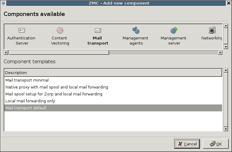
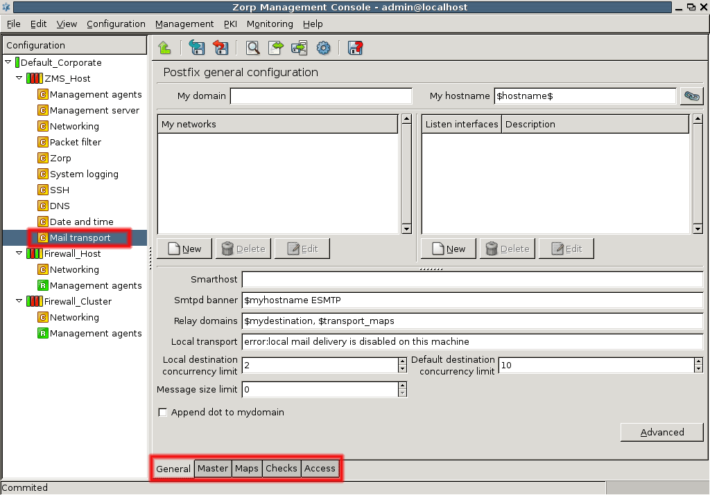
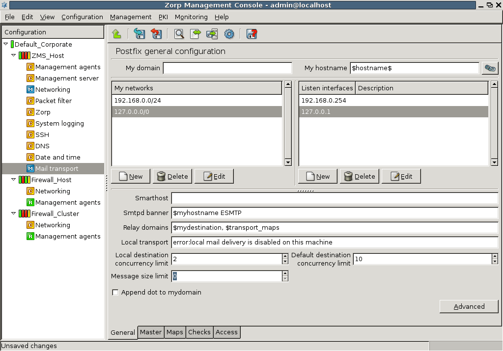
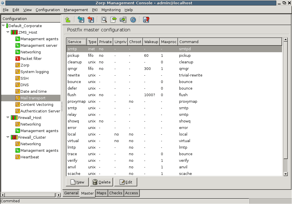
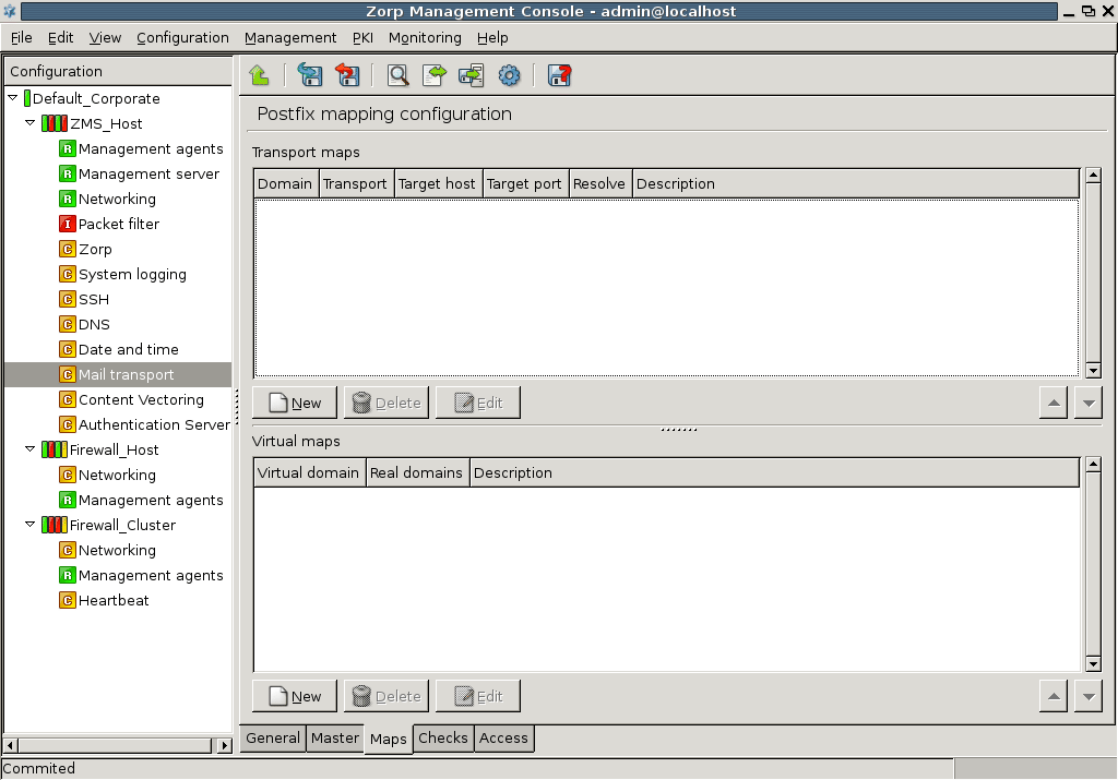
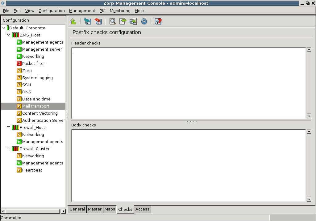
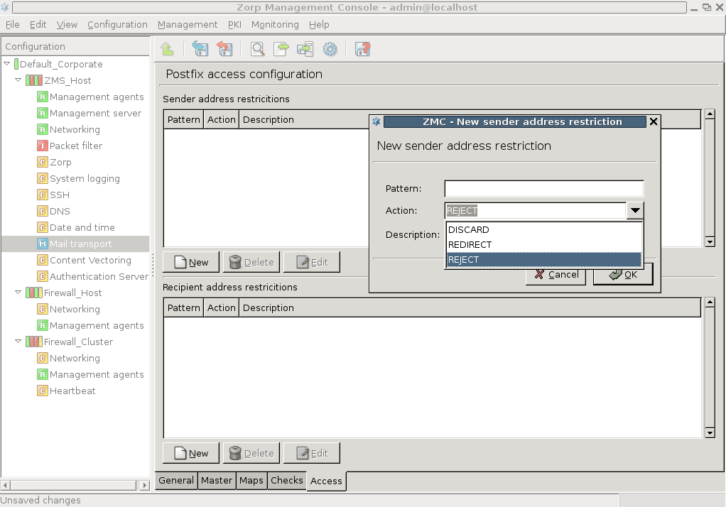
Together these tabs, actually, the files they directly correspond to, make up the majority of typical Postfix configuration.
As you see, it is technically possible to create a full featured SMTP server on the PNS machine, but it is definitely not recommended.
| Note |
|---|
Unless you have a definite reason to use the Postfix component, for example, you have complex mail routing requirements, use the SMTP proxy to perform mail proxying on your PNS firewall. |
Local services run on the elements of the PNS Gateway System: on PNS, MS, and CF hosts. PNS hosts can provide the following services locally.
| Warning |
|---|
Local services can be accessed only using IPv4. IPv6 access for local services is currently not supported. |
ssh: Enables remote SSH access to the PNS host. Opens port TCP/22.
smtp: Enables the transport of SMTP (e-mail) traffic. This local service must be enabled if you want to use the native Postfix service of PNS to handle e-mail transfer (see Section 9.3, Postfix). Opens port TCP/25.
ntp: Enables clients to synchronize their system clocks to the clock of the PNS host using NTP. This local service must be enabled if you want to use the native NTP service of PNS (see Section 9.2, NTP). Opens port UDP/123.
identreject: If enabled, PNS rejects every traffic arriving to the 113/TCP port.
dns: Enables clients to use the PNS host as a DNS server. This local service must be enabled if you want to use the native BIND9 service of PNS (see Section 9.1, BIND). Opens port UDP/53.
dns-zonetrans: Enables clients to use the PNS host as a DNS server. This local service must be enabled if you want to use the native BIND9 service of PNS and enable zone transfer (see Section 9.1, BIND). Opens port TCP/53.
zmsgui: Enables administrators to connect to MS with MC, and manage the PNS Gateway System. Opens port TCP/1314.
zmsengine: Enables communication between MS and the PNS hosts. This local service must be enabled if a host is managed from MS. Opens ports TCP/1311 and Opens port TCP/1313.
zmsagent: Enables communication between the PNS hosts and MS. This local service must be enabled on the MS host. Opens ports TCP/1310 and Opens port TCP/1312.
| Note |
|---|
PNS automatically enables the services required for the management of the host: |
Local services can be managed on the tab of the MC component. For every local service, the name, used ports, the protocol (TCP or UDP), and the parameters are displayed. The target is ACCEPT is access to the service is permitted, REJECT if it is denied. To enable access to a local service on a host, complete the following steps.
9.4.1. Procedure – Enabling access to local services
Navigate to the tab of the MC component of the host and click .
Select the service from the combobox. The port number and the type of the protocol is set automatically. Modify them only if you have a special configuration.
Select the zones permitted to access the service, then click . The packet filter rule corresponding to the new service is automatically added to the ruleset.
To activate the new service, do not forget to and the changes to the host, and to the packet filter using the icon.
PNS, in cooperation with the MS and MC software components, is designed to be fully configurable from the graphical user interface of MC. Though this graphical administration is definitely the preferred method of management, it is possible to manually accomplish all the management and configuration tasks using a simple, character–based terminal console connection. In addition, the console–based administration provides some useful tools for troubleshooting scenarios that are not available through MC.
Local firewall administration, in this sense, does not necessarily refer to administration that takes place physically at the firewall machine using its local console and keyboard, but it also refers to setups where the character terminal of the firewall is reached through a secure network connection using SSH. The described administration is local in the sense that the configuration files are directly manipulated on the firewall machine, and not through the MS database.
| Note |
|---|
|
MS reads the configuration files of the firewall host only once, when it is bootstrapped. For details, see Chapter 4, Registering new hosts. After that, configuration changes are only downloaded to the host with the help of the transfer agent and are not parsed again by MS. Therefore, if you make local changes to a configuration file which is otherwise managed by MS, your configuration changes are overwritten when you next issue an Upload command from MS. Configuration files that are not managed by MS, for example custom installed services on the firewall for which you do not define a Text Editor plugin, are not affected by this rule. |
The components of PNS Gateway run on Ubuntu-based operating systems, currently on Ubuntu 18.04 LTS. Therefore, for local management, the tools and procedures available are more or less the same as for any other Linux installation. If you install the PNS host using the installation media of , only the most essential tools and services are installed by default. Although it is technically possible to install almost any kind of Linux software on a PNS host, it is not recommended because custom installed tools may have a negative effect on the system in terms of security and stability. In fact, all local administration tasks can be accomplished by using the software tools that are available by default.
Linux is a technically sophisticated operating system that allows full access to and total control over itself for system administrators. Therefore, it is vital to have the sufficient skills and experience before administering it locally in a production environment.
| Note |
|---|
Untrained/inexperienced use can render any Linux system inoperable quickly, so take extreme care when performing local administration. |
This chapter is by no means intended to be a Linux tutorial. If you are unfamiliar with the concepts of general administration of Linux, consult some form of documentation before proceeding. There are excellent documentation available for Linux, both in printed and online forms. To avoid scattering of resources and material, the Linux Documentation Project (LDP) which manages the documentation tasks of Linux, provides a central access point to a thematically organized set of Linux documentation. Visit LDP site ( http://www.ldp.org) for more information. Although the primary language of documentation is English, a substantial part of the material is either translated or in the process of translation to other languages. If you prefer traditional, paper–based documentation forms, books on Linux administration are also available from major publishers worldwide. For more information, see Appendix C, Further readings.
A basic rule of working with any operating system is that only tasks that require system administrator (root) rights must be performed using a system administrator's account. All other tasks must be performed as a normal, non-privileged user. This is especially true for security–sensitive environments, such as a firewall.
Therefore, for every administrator of the firewall who needs local access, a normal user account must be created. Even if a firewall is managed by a team of administrators, typically only senior–level staff must be provided local logon rights. To preserve accountability and to maintain an adequate level of security, a separate account must be created for each administrator. These accounts are normal user accounts with no special privileges. However, to perform administrative tasks, special, root level access is needed to the services involved in the administrative action.
Linux provides the sudo tool to grant root level access to dedicated normal users. sudo allows the users to run only certain commands (specified by the root user) as root.
The sudo utility provides a secure method of having root level access to parts of the system. It is especially useful if there are more than one users who are potentially local administrators. To use sudo all users who need root access must be listed in the file /etc/sudoers. The sudo command then allows these users to run only certain commands (specified by the root user) as root. This selective method is more secure than providing full root level access for a user to all parts of the system. It also allows for a more granular control over user activities on the system. sudo has configurable options as well as default settings; more information on these can be found in its manual pages (man sudo).
| Tip |
|---|
You can access Linux/Unix manual pages easily from Windows environment as well. If you have a Mozilla or Firefox browser, type man sudo in the address line and the browser opens immediately the sudo project's homepage. |
Local administration of the firewall can be accomplished through either the local console itself, that is, physically sitting in front of the machine, or through a terminal session over the network. This network session obviously needs to be encrypted. PNS uses the industry–standard SSH protocol to accomplish this. SSH is a client–server protocol that provides an encrypted communication channel between the parties. PNS contains a native SSH server implementation, and SSH clients are freely available for most major operating systems. If you do not have one already installed on your system, visit http://www.freessh.org for a list of both free and payware ssh clients.
To establish an SSH session, the client must first authenticate itself to the server. A number of different authentication methods are defined in the ssh protocol standard. Currently, SSH version 2 is the latest standard version.
The simplest authentication method is password authentication: the user logging in to the SSH server provides a username/password pair that is a valid user in the server machine. The advantage of this method is its simplicity: no special configuration is needed and the user must know the username and password on the server anyway.
A more secure method of SSH login is the public key-based authentication: in this case the user possesses a public/private key pair and the server has a copy of the user's public key. The logon procedure using public keys is the following:
Using the private key, the user initiates a logon to the server with the help of a session identifier.
The server checks whether it has the matching public key for the user and grants access if both the key is found and the signature is correct.
The advantage of this method is enhanced security. No username and password have to be provided and the entire authentication session is secured with public key cryptographic procedures. The disadvantage is the extra setup needed: you have to generate user key pairs, place public keys of users on the server and the user have to carry the private keys to all client computers the user wishing to log on from, and upon leaving the client the user has to make sure to remove the private key from the computer. Although more complicated to set up, this method of authentication is preferred due to the enhanced security it provides.
By default, PNS allows password-based SSH logins, too. During setup it had to be decided whether the root user can log in to the system through SSH connection. You are recommended not to allow roots to login through SSH for security reasons. You have to establish first an SSH session as a normal user and then perform a sudo action to gain special access permission for accomplishing administrative tasks.
For more information on SSH and its configuration, see Appendix C, Further readings.
Local system configuration is performed by editing the appropriate configuration files and then reloading or restarting the corresponding service(s).
All important system components, such as daemons, services, have their own configuration files, some have more than one. These files are generally stored under the /etc directory. There are exceptions from this rule, of course, but the majority of configuration files are in that directory. Some files are directly stored under /etc, but most services store the configuration files for the services in a subdirectory. For example, PNS stores a number of configuration files under /etc/zorp.
The configuration files are usually plain-text ASCII or XML files, and can be edited with any text editor. By default,the following text editors are installed: joe, nano, and vi.
| Tip |
|---|
Before editing configuration files make backup copies, for example, using the following command:cp filename filename.bak |
| Warning |
|---|
|
PNS replaces the configuration file of several services with a symbolic link that points to a configuration file that is maintained by PNS. Do not edit such files directly, because your changes will be automatically removed when you upgrade to a new version of PNS. To edit such files properly, first break the symbolic link, and replace the broken link with a file. After that, you can edit this file. The list of files replaced with symbolic links is the following: |
Apart from special setups where you need to fine-tune various performance parameters, the network configuration is a relatively simple task under PNS. You have to provide basic IP parameters, such as IP addresses, subnet masks, default gateway. The most important configuration file for networking is /etc/network/interfaces. This file contains separate sections for all network interfaces available in the given system. The official installation procedure of PNS involves steps to configure these basic IP parameters, so in a properly installed system this file is not empty.
| Note |
|---|
|
In all files editable under MC, after you first upload a configuration file edited in MC, a 3-line comment is added at the beginning of the file. #
# This file is generated by Management Server. Do not edit!
#
|
This text warns you about that even if you edit the file manually, it is overwritten next time you upload a change in MC. Of course, if you do not plan to work with this file from MC in the future, you can safely ignore this warning.
A typical interface configuration section in /etc/network/interfaces is the following.
auto eth0 iface eth0 inet static address 192.168.1.253 netmask 255.255.255.0 broadcast 192.168.1.255 network 192.168.1.0 gateway 192.168.1.254
After editing this file and saving it, to activate your changes run the script: /etc/init.d/networking with the restart argument. This applies to all other network configuration files, too.
Another, less frequently modified file of network configuration is /etc/hostname. It contains the hostname parameter of the system. It is important for the name resolution processes initiated by various system components. Whenever a process needs name resolution, that is, to map a name to an IP address, the first thing the system does is it checks this file to see whether its own hostname has been queried. The Linux command hostname queries this file as well.
The file / etc/mailname is important for the proper operation of the Postfix native service. It must not be empty and it gets filled automatically. You can alter the value stored here, if needed.
Another network configuration file, /etc/hosts may be used for static name resolution: it stores name to IP address mappings for network hosts. Before DNS, this file was the only means to map hostnames to IP addresses. Today, most of its functionality has been taken over by DNS, but it is still useful in some scenarios. When a hostname needs be looked up, /etc/hosts is the third place the system looks for a match – the first is /etc/hostname while the second is the in-memory DNS cache. So, if you have a limited number of hosts the firewall visits often, for example, a proxy server, you are recommended to list these hosts in /etc/hosts:
#
# This file is generated by Management Server. Do not edit!
#
127.0.0.1 localhost
192.168.1.253 proxy
192.168.1.100 mail
By default, there is only one entry in this file for the hostname localhost with the IP address 127.0.0.1. This entry is needed for system boot processes, so do not delete it.
Just as with hostnames, you can name networks with symbolic names. The file /etc/networks stores these mappings. By default, this file is empty on the firewall and PNS generally does not use it.
The /etc/resolv.conf file is used by the resolver library to look up what DNS servers to query when a process needs to look up an IP address for a given hostname, or vice versa. In other words, this file lists the known nameservers for the firewall. Additionally, it contains an entry for the domain name of the firewall. This entry is also important for name resolution purposes: if, instead of a fully qualified domain name (FQDN) only a hostname is queried, the resolver automatically appends this domain name to the hostname and tries to look up the FQDN created this way.
#
# This file is generated by Management Server. Do not edit!
#
domain example.org
nameserver 192.168.1.200
This section introduces only briefly the network configuration files. For more detailed information and instructions on network configuration, see Chapter 5, Networking, routing, and name resolution, the references listed on networking in Appendix C, Further readings, and the manual pages for the mentioned files (man filename – without full path, for example: man interfaces).
Syslog-ng is the native and recommended logging service for PNS. Its configuration is stored in the /etc/syslog-ng/syslog-ng.conf file.
For more detailed information and instructions on system logging, see chapter Syslog-ng, the Syslog reference manual accessible from Appendix A, and the installed manual pages for both syslog-ng (the utility) and syslog-ng.conf (the configuration file).
After editing and saving the syslog-ng.conf file manually, restart the service by running the /etc/init.d/syslog-ng script with the restart/reload arguments. Its default configuration under PNS routes all relevant system, ISC BIND 9 and NTP messages to the /var/log/messages file and also to the console, /dev/tty8.
If you have a separate, central syslog-ng server for collecting messages from critical network hosts, such as the firewall(s), you can route (log) messages using the following steps.
-
In
syslog-ng.confon the firewall, set up a new destination of type tcp or udp, with the IP address of your syslog-ng server.Example 10.1. Specifying the target IP address of a TCP destination The IP address of the syslog-ng server is 10.20.30.40 in this example.
destination d_tcp { tcp("10.20.30.40" port(1999); localport(999)); };Supplying port information is optional; if you do not set port number, the default ports are used.
-
Decide what sources (s1, s2 here) should be logged to the syslog-ng server and set up a log path accordingly. Note that filters are optional.
log { source(s1); source(s2); filter(f1); destination(d_tcp); }; -
Define a source on the syslog-ng server with the IP address of the firewall sending log messages.
Note Specify the port numbers carefully. The corresponding ports must match on both sides.
The Network Time Protocol (NTP) is used for synchronizing system time with reliable time servers over the Internet. The synchronization is performed by a dedicated service, the ntp daemon (ntpd). The configuration file of ntpd is the /etc/ntp.conf file. The ntp.conf configuration file is read at initial startup by the ntp daemon in order to specify the synchronization sources, modes and other related information.
Unlike the system logging and network configuration files, ntp.conf does not have a manual page in the default installation of PNS. However, there are many useful sources available on NTP, see for details Chapter 9, Native services, the website of NTP protocol/service link in Appendix C, Further readings, RFC 1305 on NTP ver 3, and the manual page of ntp.conf for accessing it on other Unix/Linux installations or on the Internet.
NTP itself can have a very sophisticated configuration with, for example, public key authentication, access control, or extensive monitoring options. At the very minimum, define a time server with which the firewall can synchronize time (the server key) .
Add the following line in the configuration file.
server 10.20.30.40
| Note |
|---|
If you supply more than one timeserver, the system time is more accurate, because during a time update all the listed servers are queried and a special algorithm selects the best (most accurate) of them. |
Additionally, since PNS can be used as an authentic time source for the network, you can limit the number of concurrent client connections using the clientlimit key, and you can set a minimum time interval a client can synchronize time with the firewall using the clientperiod key.
After editing and saving the ntp.conf file manually, restart the service by running the /etc/init.d/ntp script with the restart argument. NTP can be chrooted as well, in which case the place of the configuration file is /var/chroot/ntp/etc/. You can edit the configuration here directly or you can work with the original configuration file. In the latter case the jailer script updates the configuration inside the chrooted (jailed) environment. The jailer update process involves the following three steps.
The original configuration file is modified.
Jailer is run.
The process (daemon) is restarted.
If you use MC for system configuration, the configuration files are automatically created inside the chrooted environment, so no special intervention is needed.
This method for updating jailed environments is the same for all other daemons that are to be jailed under PNS, such as ISC BIND 9.
System time is updated with the ntpdate command. Run the command as root, as usually from a system startup script so that system time gets adjusted during bootup. You can run the command manually, if needed.
BIND 9 is the official DNS server solution in PNS. BIND under PNS always runs in a chrooted environment, so its configuration file(s) are stored under the /var/chroot/bind9/etc/bind/ directory.
BIND 9 introduced the notion of split-DNS installations where basic access control can be applied to DNS Zone records. That is, for each record in the DNS database file you can specify whether outside resolvers can query those records („public” records in DNS terminology) or they are only available to internal resolver clients („private” records).
Choosing split-DNS setup is optional. In this case there are two configuration files:
named.conf, andnamed.conf.shared.
The named.conf.shared file hosts information that is intended to be public, that is, accessible to outside resolvers.
| Tip |
|---|
Setting up a split-DNS configuration only makes sense if the firewall is going to be an authoritative nameserver for one or more domains. If it is only used as a forward-only, split-DNS is not necessary. |
In forward-only configurations, only the named.conf file is used. Being a forward-only server, the nameserver under PNS does not perform recursive name resolution on the Internet for the internal clients, but instead it forwards queries as-is to the nameserver(s) configured as its forwarder(s).
This is probably the simplest functional named configuration possible, as only a single entry has to be edited in the configuration file.
forwarders {
  10.20.30.40; //IP address of the forwarder nameserver
};
You can use BIND 9 as a slave nameserver. In this setup, you do not maintain zone information on the firewall, instead, pull zone database records from an authoritative master nameserver through the zone transfer process. This setup provides fault tolerance, since if the master nameserver fails, the slave still contains a more or less up-to-date copy of the zone database.
The daemon running the BIND service is called named (hence the name for the configuration file), but the directory of the configuration file is still called bind.conf, after the name of the original Berkeley Unix implementation of the service. The startup script for the service is also called /etc/init.d/bind9.
For further information on BIND, see Chapter 9, Native services, and the references listed in Appendix C, Further readings.
10.8. Procedure – Updating and upgrading your PNS hosts
PNS uses the apt package manager application to keep the system up-to-date. Security and maintenance updates and product upgrades are all performed with apt. To update any host of your PNS Firewall solution (including PNS firewall hosts, AS and CF hosts, as well as your MS server), complete the following steps.
For more information on apt, see the apt-get manual page.
-
Update the the apt sources of the host. Use one of the following methods:
To upgrade from a DVD-ROM: Download the latest ISO file from the website, mount the DVD-ROM on the host, and execute the following command as root: >:~#apt-cdrom add
-
To upgrade from the official apt repositories from the Internet: Edit the
/etc/apt/sources.list.d/zorp.listfile and add the URLs of the package sources to download.For details on the required sources, see Procedure 4.2, Upgrading PNS hosts using apt in Proxedo Network Security Suite 1.0 Installation Guide.
Warning Do not remove Ubuntu sources from the
/etc/apt/sources.listfile. These are necessary for upgrading the base operating system.
-
Enter the following two commands.
>:~#apt-get update
>:~#apt-get dist-upgrade
The first command updates apt's package database and downloads changed packages, and the second command performs the upgrade itself.
The rest of the process is done automatically.
The packet filter configuration is stored in the /etc/iptables.conf file. Although it is technically possible to edit this file manually, you are not recommended to do so as the first two comment lines of the file warns you, even if you choose manual configuration over MC-based graphical work.
#
# This file is generated automatically from iptables.conf.in and iptables.conf.var.
# Do not edit directly, regenerate it using iptables-gen.
To make packet filter configuration more error–resistant and easier, a frontend utility pack, the iptables-utils has been created where a couple of scripts help the creation and maintenance of packet filter rulesets. For more details on the iptables-utils, see chapter Packet Filtering.
| Tip |
|---|
Using iptables-utils is absolutely beneficial in the long term as the number of system closeouts, that is administrator lock-outs happens for example by activating an incorrect packet filter ruleset, can be dramatically decreased. It is favourable especially if you are far away from the firewall. |
After installing the firewall a default ruleset is active. Since PNS acts as a default-deny firewall, the ruleset allows only connections from the MS host machine specified during installation to the firewall and the outgoing connections originating from the firewall itself. Besides the iptables.conf file which stores the currently active ruleset, the iptables.conf.in file is also present in the system (/etc/iptables.conf.in) so you can see the differences between the two. The / etc/iptables.conf.var file is also stored containing a single statement.
#define MSHOST <ip_address>
This entry allows you to refer to the MS host machine by the name MSHOST rather than by its IP address when editing the iptables.conf.in file. These tools and the intermediate configuration files greatly help the administration of packet filter rulesets. However, an in-depth knowledge of iptables is still needed for the successful management of the packet filter.
For more information, see Appendix A, Packet Filtering on PNS-specific configuration of IPTables, the installed manual pages of iptables (userland utility), and the documentation of Netfilter/IPTables project including a detailed tutorial and HOWTO documents accessible from Appendix C, Further readings.
The networking configuration of the firewall which involves IP addresses, hostnames, and resolver configuration, usually changes rarely. However, the daily administration of the firewall often requires the changing of the actual ruleset. For more information on this process, see section Creating PNS Policies.
Basically, the process can be divided into the following two main parts.
Configuring the necessary service definition(s).
Creating the matching packet filter ruleset, that is generating a skeleton.
The latter packet filter manipulation procedure is detailed in section Packet filter, above. This section shows how to edit a service definition locally.
The key configuration files needed are stored in the /etc/zorp directory. The following files play the most important roles in the configuration.
-
policy.pycontaining complete service definitions
-
instances.conflisting the instances used in the firewall together with their parameters
| Tip |
|---|
|
In the default installation of PNS there are two commented sample files, To learn command-line policy management it is a good idea to first use MC to graphically generate test-policies and then to check the generated policy files through a terminal connection. |
For background information on the possible contents of these files, see Chapter 6, Managing network traffic with PNS.
The configuration of PNS is based on the Python programming language. The configuration file ( policy.py) is a Python module in itself. This does not mean, however, that you have to learn Python, knowing the syntax of the language and a few semantic elements is sufficient. Though the configuration file may not seem like a complete Python module, it is important to know that it is parsed as one. So the following syntactical requirements of Python apply:
Indentation is important as it marks the beginning of a block, similar to what curly braces ('{}') do in C/C++/C#/Java. This means that the way you indent blocks must be consistent for that given block. The below example shows a correct syntax first followed by an incorrect syntax.
Correct:
if self.request_url == 'http://www.balasys.hu/':
  print ('debug message') return HTTP_REQ_ACCEPT
return HTTP_REQ_REJECT
Incorrect:
if self.request_url == 'http://www.balasys.hu/':
   print ('debug message')
  return HTTP_REQ_ACCEPT
return HTTP_REQ_REJECT
Getting used to correct indentation is probably the most important Python task for a beginner, especially if you have not done any C or C-like programming before. Indentation in Python is the only way to separate blocks of code since there are no Begin and End statements or curly braces. Otherwise, the language itself is quite simple and easy to learn. Note that Python is case-sensitive.
For more information on Python, see Appendix C, Further readings.
The Policy.py file has a strict structure that you must obey when modifying the configuration manually. It consists of the following code modules:
Import statements
Zone definitions
Class configurations
NAT policy settings
Authentication policy settings
Instance definitions
These modules are of varying length, depending on the complexity of the policy configuration.
10.10.1.1. Procedure – Edit the Policy.py file
-
Set the import statements.
If you look at the default-installed
policy.py.samplefile you can see that it starts with the import statements:from Zorp.Core import * from Zorp.Plug import * from Zorp.Http import * from Zorp.Ftp import *
These statements mean that one or more required (Python) front-end modules are imported to the configuration. Zorp.Core is essential, the other three imports are there because the sample file contains references to these three proxy classes.
Tip A good way of learning
policy.pyis to create firewall policies in MC and then look at the resulting configuration files. -
Provide the name of the firewall, and the zone definitions along with the access control you defined for them, that is, the allowed outbound and inbound services.
Zone("site-net", ["192.168.1.0/24"]) -
Configure the classes used in service definitions.
These class definitions can be simple, with, in essence, naming the proxy class to be used, that is, to be derived from only; like the IntraFtp class in the sample file:
class IntraFtp(FtpProxy):
  def config(self):
    FtpProxy.config(self)
Or, they can be rather complex, customizing the derived proxy class with attributes, as in the case of the IntraHttp class in the sample file:
# Let's define a transparent http proxy, which rewrites the # user_agent header to something different. # class IntraHttp(HttpProxy): def config(self): HttpProxy.config(self) self.transparent_mode = TRUE self.request_headers["User-Agent"] = (HTTP_HDR_CHANGE_VALUE, "Lynx/2.8.3rel.1") self.request["GET"] = (HTTP_REQ_POLICY, self.filterURL) # self.parent_proxy = "proxy.site.net" # self.parent_proxy_port = 3128 # self.timeout = 60000 # self.max_keepalive_requests = 10 def filterURL (self, method, url, version): # return HTTP_REQ_REJECT here to reject this request # change self.request_url to redirect to another url # change connection_mode to HTTP_CONNECTION_CLOSE to # force kept-alive connections to close log("http.info", 3, "%s: GET: %s" % (self.session.session_id, url)) -
Define the instances to be used.
Besides its name, the most important characteristic of an instance is the list of services it provides. Therefore, define services within the instances:
# zorp_http instance
def zorp_http () :
  # create services
  Service(name='intra_http', router=TransparentRouter(), chainer=ConnectChainer(), proxy_class=IntraHttp, max_instances=0, max_sessions=0, keepalive=Z_KEEPALIVE_NONE)
  Service(name='intra_ftp', router=TransparentRouter(), chainer=ConnectChainer(), proxy_class=IntraFtp, max_instances=0, max_sessions=0, keepalive=Z_KEEPALIVE_NONE)
  Rule(proto=6,
    dst_port=80,
    service='IntraHttp'
    )
  Rule(proto=6,
    dst_port=21,
    service='IntraFtp'
    )
Still within the instance definition code block, with correct indentation, specify the firewall rules that will start these services.
These blocks, the zone definition, proxy class definition, instance definition, service definitions, and rule definitions make up the policy.py file. The provided example is simple, yet it provides a lot of information on the correct syntax and on the
possible contents of the policy.py file.
The other configuration file, instances.conf is much more simple: it lists the instances to be run, and supplies some runtime arguments for them such as log level. The only compulsory argument for running an instance is the name of the Python file containing the corresponding instance definition. Although the example uses a single policy file ( policy.py) to store all definitions, it is possible to separate the policy to different .py files if it makes maintenance or archiving easier.
In the following example instance definitions are separated into two files, policy-http.py and policy-plug.py:
#instance arguments
#zorp_http --verbose=5 --policy /etc/zorp/policy-http.py
#zorp_plug --policy /etc/zorp/policy-plug.py
For more information on the configuration files, see the manual pages for instances.conf and Application-level Gateway (man instances.conf and man zorp — installed by default on PNS) and Proxedo Network Security Suite 1.0 Reference Guide, published by . It is available on the PNS CD-ROM and can also be downloaded from https://docs.balasys.hu/.
Starting and stopping firewall instances is performed automatically using the default installation. However, you can control manually the firewall instances with the zorpctl utility. Zorpctl starts and stops PNS instances using the instances.conf file. One or more instance names can be passed to zorpctl as arguments. If an error occurs while starting or stopping one of them, an exclamation mark ('?') is appended to the name of the instance as the script processes requests.
To control Application-level Gateway with zorpctl, enter the following lines.
zorpctl start|stop <instance name> <instance name> <...>
Besides the start and stop parameters for controlling instances, zopctl has some other parameters as well.
-
zorpctl status <instance>printing the status of the specified PNS instance
-
zorpctl szig <instance>displaying some internal information about the specified PNS instance
-
zorpctl inclog <instance>incrementing the logging level of the specified instance with one level
-
zorpctl declog <instance>decrementing the logging level of the specified instance with one level
For a full list of the available parameters with short explanations type zorpctl at a command prompt, without parameters, or issue the man zorpctl command. The manual page of zorpctl is also available at zorpctl(8) in Proxedo Network Security Suite 1.0 Reference Guide.
The use of cryptography, encryption and digital signatures is becoming more and more widespread in electronic communication. Nowadays they are an essential part of e-business and e-banking solutions, as well as other fields where the identity of the communicating parties has to be verified. Communication through secure (encrypted) channels is also becoming increasingly popular. This chapter offers a brief introduction into the fields of cryptography and the public key infrastructure (PKI), describing how they can be used for authentication and secure communication, and the PKI system developed for MS to support them.
The goal of using encryption in communication is twofold: to guarantee the privacy of the communication, so that no third party can acquire the information, and to verify its integrity — to make sure that it was not damaged (or deliberately modified) on the way. Privacy can be guaranteed by the use of encryption algorithms, while integrity protection requires the application of hashing algorithms. Secure communication utilizes both of these techniques.
The main concepts and requirements of secure communication are the following:
Both the sender and the receiver of the message have access to the algorithm (this is practically a piece of software, often used transparently to the actual user) that can be used to encrypt and decrypt the message.
Both have access to a special piece of information — so called key — that is required to encrypt and to successfully decrypt the message.
An encrypted message cannot be decrypted without the proper key, even if the encryption algorithm is known.
The receiver can identify if the encrypted message has been damaged or modified. (Remember, it is not necessary to understand the message to mess it up.)
Both the sender and the receiver can verify the identity of the other party.
There are two main categories of encryption methods for ensuring privacy: symmetric and asymmetric encryption.
Symmetric encryption algorithms use the same key for the encryption and decryption of a message, therefore the same key has to be available to both parties. Their advantage is their speed, the problem is that the key has to be transferred to the receiver somehow. The keys used in symmetric encryption algorithms nowadays are usually 128-256 bit long.
Asymmetric encryption methods use different keys for the encryption and the decryption of a message. The sender generates a keypair, messages encrypted with one of these keys can only be decoded with the other one. One of these keys will be designated as the private key, this will be used to encrypt the messages. The other key, called public key is made available to anyone the sender wishes to send messages to. Anyone having access to the encrypted message and the public key can read the encrypted message and be sure that it was created with the appropriate private key. Certain encryption algorithms (like RSA) make it also possible to encrypt a message using the public key, in this case only the owner of the private key can read the message. The disadvantage of asymmetric encryption is that it is relatively slow and computation intensive. A suitable infrastructure for exchanging public keys is also required; this is needed to verify the identity of the sender, confirming that the message is not a forgery. This topic is discussed in Section 11.1.1.3, Authentication and public key algorithms The length of the keys used in asymmetric encryption ranges from 512 to 4096 bits.
| Tip |
|---|
It is recommended to use at least 1024 bit long keys. |
Being able to decrypt a message using the appropriate public key guarantees only that it was encrypted with its matching private key. It does not mean that the person (or organization) who wrote the message is who he claims to be — that is, the identity of the sender cannot be verified this way. Without an external way to successfully verify the identity of the other party, this would make communication based on public key algorithms susceptible to man-in-the-middle attacks. To overcome this problem, the identity of the other party has to be confirmed by an external, trusted third party. Two models have evolved for that kind of identity verification: web of trust and centralized PKI.
In a web of trust based system (such as PGP), individual users can sign the certificate (including the public key and information on the owner of the key) of other users who they know and trust. If the certificate of a previously unknown user was signed by someone who is known and trusted, the identity of this new user can be considered valid. Continuing this scheme to many levels, large webs can be built. Web of trust does not have a central organization issuing and verifying certificates — this is both the strength and weakness of such systems.
In centralized PKI — as its name suggests — there are certain central organizations called Certificate Authorities (CAs) empowered to issue certificates. Centralized PKI systems are described in detail in Section 11.2, PKI Basics.
In real-world communication, the two types of encryption are used together: a (symmetric) session key is generated to encrypt the communication, and this key is exchanged between the parties using asymmetric encryption.
The general procedure of encrypted communication is the following:
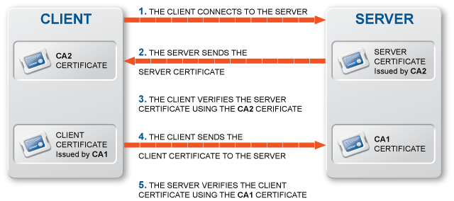
11.1.1.4.1. Procedure – Procedure of encrypted communication and authentication
The sender and the receiver select a method (encryption algorithm) for encrypting the communication.
The sender authenticates the receiver by requesting its certificate and public key. Optionally, the receiver can also request a certificate from the sender, thus mutual authentication is also possible. During the handshake and authentication the parties agree on a symentric key that will be used for encrypting the data communication.
The sender encrypts his message using the symmetric key.
The sender transmits the message to the receiver.
The receiver decrypts the message using a symmetric key.
The communication between the parties can continue by repeating steps 3-5.
Another important aspect is that suitable keys have to be created and exchanged between the parties, which also requires some sort of secure communication. It also has to be noted that — depending on the exact communication method — the identity of the sender and the receiver might have to be verified as well.
The strength of the encryption is mainly influenced by two factors: the actual algorithm used, and the length of the key. From the aspect of keylength, the longer the key is, the more secure encryption it offers.
Hashing is used to protect the integrity of the message. It is essentially a one-way algorithm that is capable of creating a fixed-length extract of the message (or document). This extract (hash) is:
specific to the given document,
changing even a single bit in the document changes the hash,
it is not possible to predict how a certain change in the document modifies the hash (that is, it is impossible to predict the hash),
it is not possible to recover the original document from the hash.
A digital signature is essentially the hash of the signed document, encrypted by the private key of the signer. The genuineness of the document can be verified by generating the hash of the document received, decrypting the signature using the public key of the sender, and comparing the hash contained in the signature to the one generated from the received document. If the two hashes are identical, the document received is the same as the one sent by the sender, and has not been modified on the way.
The purpose of PKI system is to provide a way for users to reliably authenticate each other. This requires the users to have private-public keypairs (as described in Section 11.1.1.2, Asymmetric encryption), some sort of certificate to verify the users identity, and a system to manage and distribute keys and certificates. For verifying the identity of a user, either centralized PKI systems, or webs of trust can be used.
The centralized model is based on authorizing institutes, so called Certificate Authorities (CA) to verify the identity of the user or organization and certify it in a digital certificate. Since there is no single, worldwide CA guaranteeing the identity of everyone, the identity of a party can be considered valid if its certificate was signed by a trusted CA. A trusted CA is a CA that has been decided to be trustworthy, there is no general algorithm or method to determine which CAs can be trusted. A 'trusted CA list' includes the certificates of all the CAs deemed trustworthy.
CAs themselves also have to certify their identity, meaning they also need certificates. These certificates are usually signed by another, higher level CA. This allows for hierarchies of CAs to be created, in a way that although a CA might not be explicitly trusted (because it is unknown, therefore it not on the list of trusted CAs), but the higher-level CA that signed its certificate might appear on the list (which makes the lower-level CA trustworthy).
Obviously, using this method alone is not sufficient, since it always requires a higher-level CA. Therefore, self-signed CA certificates also exist, meaning that the CA itself has signed its own certificate. This is not uncommon; a CA with a self-signed certificate is called a root CA, because there is no higher-level CA above it. To trust a certificate signed by this CA, it must necessarily be in the 'trusted CAs' list.
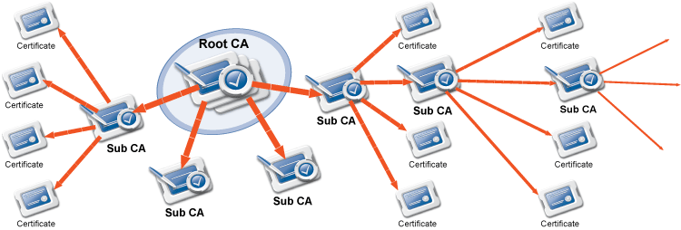
| Note |
|---|
To allow easier management, the trusted CA lists usually contain only root CAs. |
A digital certificate is a digital document conforming to the X.509 standard that certifies that a certain public key is owned by a particular user or organization. This document is signed by a third party (the CA). This data file contains the public key of its owner, as well as the following information:
/: Validity (from/to date) of the certificate.
: For what end may the certificate be used (for example, digital signature, data encryption, and so on).
: The Distinguished Name of the Certificate Authority that signed the certificate.
: The Distinguished Name of the owner of the certificate.
-
: The distinguished name (DN) usually contains the following information (not all the fields are mandatory, and other optional fields are also possible). A DN is often represented as a comma-separated list of fieldname-value pairs.
Country: 2-character country/region code.
State: State where the organization resides.
Locality: City where the organization resides.
Organization: Legal name of the organization.
Organizational Unit: Division of the organization.
Common Name: The common name is often the address of the website or the domain name of the organization, for example, www.example.com, or the name of the user in case of personal certificates.
When an organization wishes to create a certificate, it has to perform the following:
11.2.3.1. Procedure – Creating a certificate
-
Generate a private-public keypair.
Tip The secure storage of private keys has to be solved.
Prepare a certificate signing request (CSR). For filling the request form, the information contained in the distinguished name has to be provided (for example, common name, organization, and so on).
The CSR is bundled together with the public key of the generated keypair.
The organization selects a CA to sign the certificate request. The CSR has to be submitted to a special department of the CA, called Registration Authority (RA).
-
The RA verifies the identity of the requestor.
Note Submission of the CSR to the RA and the identity verification involves physically visiting the RA with all the papers it requires for verifying the identity of the organization and its representative (for example, documents of incorporation, ID cards, and so on).
-
If the RA confirms the identity of the requestor, the CA signs the request using its private key, and issues the certificate.
Tip If the certificate is to be used only internally (as in the case of PNS components), an own CA with a self-signed certificate can be set up to sign the certificates.
The requestor can now import and use the certificate on his machines.
If a certificate loses its validity or becomes obsolete, it should not be accepted anymore and is to be revoked or refreshed.
Basically the CA has the following functions:
Checks the identity of everyone requesting a certificate.
Confirms the identity of a user by its signature.
Monitors the validity of issued certificates (see Section 11.2.4, CRLs below).
| Tip |
|---|
Although to efficiently use certificates over the Internet they need to be signed by well-known Certificate Authorities, this is not required if they are used only locally within an organization. For such cases, the organization itself can create a local (internal) CA and sign the certificate of this CA. This CA having a self-signed certificate (thus it becomes the local root CA) can then be used to sign the certificates used only internally. |
CRL stand for Certificate Revocation List: it is a list containing the serial numbers and distinguished names of certificates that cannot be trusted anymore and were hence revoked. If a certificate loses its validity for any reason (for example, becomes compromised because its private key is stolen, and so on) the issuing CA revokes it. This is published on the website of the CA in a CRL. Obsolete or invalid certificates should be revoked even if they are used only internally.
CRLs can be obtained usually through HTTP, certificate authorities update and publish them on their website on a regular basis.
To decide whether a given certificate is valid or not, the followings have to be checked:
-
It was signed by a trusted CA.
Note If the certificate of the CA signing the given certificate was signed by a trusted CA (or by another CA lower in the CA chain), the certificate can be trusted. Sometimes this CA chain can consist of several levels.
It is not out-of-date.
It has not been revoked (that is, it does not appear on the up-to-date CRL).
The purpose of the certificate is appropriate, that is, it is used for the issued intention.
| Note |
|---|
It is possible to submit CSRs to more than one CA (and have them signed) using the same public key. However, it is considered to be highly unethical, likely resulting in the revocation of all of the certificates involved. |
Authentication with certificates is accomplished by checking the validity of the certificates of the communicating parties.
One-way authentication: One of the parties (typically the client) requests a certificate of the server and checks its validity.
Mutual (two-way) authentication: Both the client and the server check the validity of the other's certificate. Generally both parties must own a trusted certificate (that is, a certificate signed by a trusted certificate authority).
SSL provides endpoint authentication and communications privacy, as well as possibility for one-way or mutual authentication using certificates. The protocol allows client/server applications to communicate without being subject to eavesdropping, tampering, or message forgery. SSL runs on layers beneath application protocols (for example, HTTP, SMTP, and so on) and above the TCP transport protocol. SSL is able to use a number of symmetric and asymmetric encryption algorithms. The certificates used in the communication must conform to the X.509 standard.
IPSec is a set of protocols for securing packet flows and key exchange by encrypting and/or authenticating all IP packets. As IPSec is an obligatory part of IPv6 (and optional in IPv4), it can be expected that it will become increasingly widespread. IPSec provides end-to-end security for packet traffic — even for UDP packets, because it operates over the IP layer. In PNS, IPSec is used to construct Virtual Private Networks (VPNs). Please refer to Chapter VPN for more details.
| Note |
|---|
PNS supports the use of the Secure Sockets Layer (SSLv2 and SSLv3), Transport Layer Security (TLSv1) and IP Security (IPSec) digital encryption protocols. |
When importing/exporting keys and certificates, they can be stored in various file formats. MS supports the use of the PEM, DER, and PKCS12 file formats. The main differences between them are summarized below.
-
PEM: PEM (Privacy Enhanced Mail) is an ASCII text format that can store all parts of the certificate, that is, certificate, CSR, CRL, private key (which can be optionally protected with a password). It is not necessary to store all parts in a single file.
Tip If nothing restricts it, it is recommended to use the PEM format.
DER: The DER (Distinguished Encoding Rules) format stores any single part of a certificate in a binary file.
PKCS12: The PKCS12 (Public Key Cryptography Standards) is a binary file format developed to provide an easy and convenient way to backup or transport certificates. The file always contains a password-encrypted private key and the associated certificate.
The purpose of including a light-weight PKI system in MS is to provide a convenient and efficient way to manage and distribute certificates and keys used by the various components and proxies of the managed PNS hosts. It is mainly aimed at providing certificates required for the secure communication between the different parts of the firewall system, for example, PNS hosts and MS engine (the actual communication is realized by agents). The PKI of MS also provides a consistent and convenient tool to manage both internal and external certificates between the firewalls. MS can be set to perform the regular distribution of certificates and CRLs automatically, ensuring that no invalid or revoked certificate can be used.
| Note |
|---|
It has to be noted that the PKI of PNS is not a general purpose PKI system, consequently it is not recommended to be used as such. It was designed and intended for internal use between the components of the firewall system (to secure the communication between PNS hosts and MS servers, monitoring agents, and so on), and to manage external certificates available on the managed hosts. |
| Tip |
|---|
The PKI system of MS can also manage certificates signed by external CAs. This is useful because MS provides an efficient way to handle the distribution of certificates among the managed hosts. |
Management of the PKI system is slightly different from managing other components. Locking of the PKI component is site-based, that is, when an administrator starts to modify the PKI settings of a host (either on one of the Edit Certificates panels or the Site preferences), the whole site is locked from other administrators. Changes are committed automatically.
MS manages the certificates, their accompanying keys, as well as the related CSR and CRL(s) as a single entity, therefore when using key, certificate, CSR or CRL in connection with MS, this single entity containing all of them referred. This is important to remember even if not explicitly stated in the text.
In MS, a certificate entity has two different names, these are:
Unique name: The unique name is the name used to unambiguously identify the certificate entity(and its different parts) in MS. This name does not appear in the certificate, it is required only for management purposes.
Distinguished name: The distinguished name (DN) of the owner of the certificate. (Sometimes only the Common Name part is showed.) See Section 11.2.2, Digital certificates.
The owner host is the machine allowed to use the private key. (For example, when specifying on a host which certificate should be used for authentication to management agents, only the certificates owned by the given host can be selected.) It is important to set the owner host of a certificate otherwise it would be impossible to use that certificate entity for all purposes (like authentication).
Distribution of certificates can be handled automatically by MS. MS examines which certificates are used by the given host, and deploys only those. This ensures that certificates are not unnecessarily present on all machines.
Any part of the certificate entity has to be deployed to the proper host in order to be used. Two main rule governs the distribution (deployment) of certificate entities:
Every certificate entity is distributed only to those hosts that actually use it, and only the used parts are deployed.
The private key can be used only on the host(s) that are set as the owner host of the certificate entity. (Therefor the private key is only distibuted to the owner host of the certificate entity.)
| Note |
|---|
|
CAs do not belong to a single host, but to the whole site, therefore their certificate entity (including their private key) can be made available on each host. Certificates (not the full entity, only the certificate part) can be distributed everywhere. |
| Warning |
|---|
Distribution should only be performed for complete, consistent settings. Distributing incomplete or only partially refreshed configuration can lead to lockouts. This is especially true when regenerating the keys of transfer agents. To prevent such situations, it might be useful to disable the automatic distribution when making large modifications to the PKI system, and re-enable it only after the new configuration is finished. |
Trusted CAs can be organized into so called trusted groups for more convenient use, especially for configuring proxies using certificates for authentication. In MS policies, CAs are referenced through the trusted groups containing them.
| Tip |
|---|
The use of trusted groups is useful for example when configuring SSL proxying, especially if connection only to servers having a certificate issued by a well-known and trusted CA (that is, not self-signed) is permitted. For more information on SSL, see the PNS Reference Guide. |
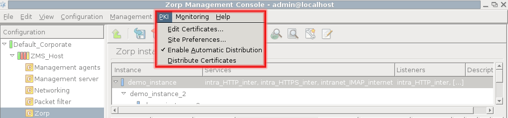
The PKI system of MS can be accessed using the menu of the main menu bar. The following sections introduce the function and use of each menu item.
The menu can be used to apply site-wide parameters to the CAs. These parameters are:
: Starting time and interval of the automatic certificate distribution, that is, at what time should the distribution of certificates and CRLs start, and how often it should be performed.
| Tip |
|---|
It is recommended to perform automatic distribution every 4 or 6 hours. |
: The fields of the DN filled here will be automatically filled when creating new CA certificates or CSRs, which is especially useful if a large number of certificates have to be created.
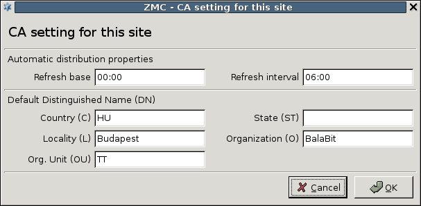
The automatic certificate distribution can be enabled from the menu, and will be performed based on the parameters set under the menu item. Manual distribution can be performed by selecting from in the main menu. When distributing CA certificates, the CRLs are also distributed.
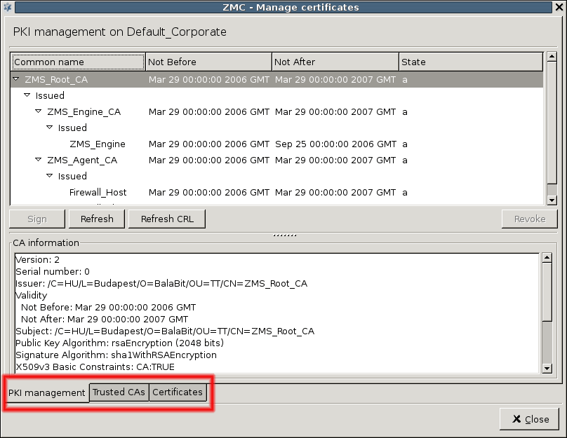
Most of the actual PKI-related tasks can be performed using the menu item. Selecting this item displays the PKI management window of the selected site. This window has the following tabs:
is used for managing local CAs. This includes managing certificates and certificate signing requests, refreshing keys, and so on
is for managing trusted certificate authorities, creating new ones, grouping them, and so on
is for managing certificates: creating new CSRs, as well as for importing/exporting certificate entities.
On all three tabs, information about the currently selected certificate (or CA certificate) is displayed in the lower section of the panel. This information includes data such as:
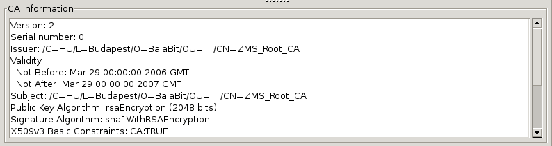
Distinguished name of the CA issuing the certificate.
Subject of the certificate.
Validity period of the certificate.
Information on the algorithm used to generate the keys, including the length of the key.
-
Any X.509 extensions used in the certificate.
Note The X.509 standard for certificates supports the use of various extensions, for example, to specify for which purposes the certificate can be used, and so on For details on the possible extensions, see Appendix C, Further readings.
Navigation window: a tree-like navigation window displaying the managed internal CAs. On a newly installed system only local CAs created by default are available. Expired certificates are shown in red.
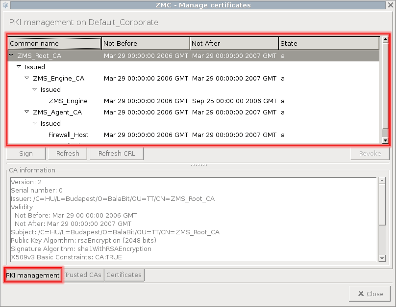
The internal CAs have small arrows that can be used to display the certificates issued and revoked by the CA.
For a given certificate, the following information is displayed:
Common name of the certificate
Validity (not before and not after)
-
State: active (a) or pending (p). A certificate becomes pending if the certificate of the CA issuing it (or the certificate of a CA higher in the CA chain) is refreshed. A certificate has to be refreshed if its validity period has expired, even if its private key has not changed. This is because the hash of the refreshed certificate is different from the old one.
Warning When the certificate of a CA is refreshed, all certificates issued by the CA has to be refreshed (re-issued) as well. If the CA has issued certificates for subCAs, then also the certificates issued by these subCAs have to be refreshed.
Command bar: contains the different commands that can be issued for the certificate or CA selected. The available commands are:
: available only for internal CAs, used to sign CSRs. After clicking on it, a list of unsigned CSRs is displayed. The list shows the distinguished names of the CSRs. Parameters for the certificate to be signed can be overridden here (period of validity, X.509 extensions, and so on).
-
: This command can be used to refresh certificates, that is, to renew them by extending their validity period if expired, or also to create new keys to the certificate. Key generation is only performed if the checkbox is selected.
Tip It is recommended to regenerate the keys as well when refreshing a certificate for any reason.
: available only for CAs. The CRL of the CA is valid until the time specified. The refreshed CRL will only be used on the managed hosts after distribution. MS distributes certificate entities, that is, when distributing certificates the corresponding CRLs are automatically distributed as well.
-
: available only for certificates signed by an internal CA. Marks the certificate as invalid and adds it to the CRL of the CA. CA certificates can also be revoked this way.
Note Self-signed certificates (that is, certificates of local root CAs) cannot be revoked.
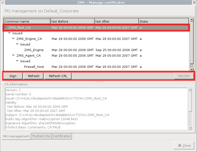
The table below briefly summarizes the CAs created and used by default in PNS.
| Name of the CA | Purpose |
|---|---|
MS_Root_CA
|
The Root CA of PNS, used to sign certificates of all other local CAs in PNS. |
MS_Engine_CA
|
Signs the certificate of the MS engine. |
MS_Agent_CA
|
Signs certificates of the transfer agents. |
Table 11.1. Default CAs and their purpose
For details on configuring agent and engine certificates, please refer to Chapter 13, Advanced MS and Agent configuration.
This menu item is for managing certificate authorities. The upper section of the panel displays the list of available CAs, both internal and external. Apart from creating the default internal CAs, the certificates of a number of trustworthy external ones (for example, VeriSign, NetLock) is imported as well. The following information is displayed on each:
-
: Components of the certificate entity available for the CA.
c: certificate. Usually this is the only part available for external CAs.
k: private key of the certificate.
r: CSR.
l: CRL of the CA.
An internal CA is fully functional if all of its parts are available (CRL is optional) .
: Name(s) of the trusted groups that the CA is member of.
: Validity of the CAs certificate.
: Date until the CRL of the given CA is valid. If this field is empty, no CRL has been released by the CA so far.
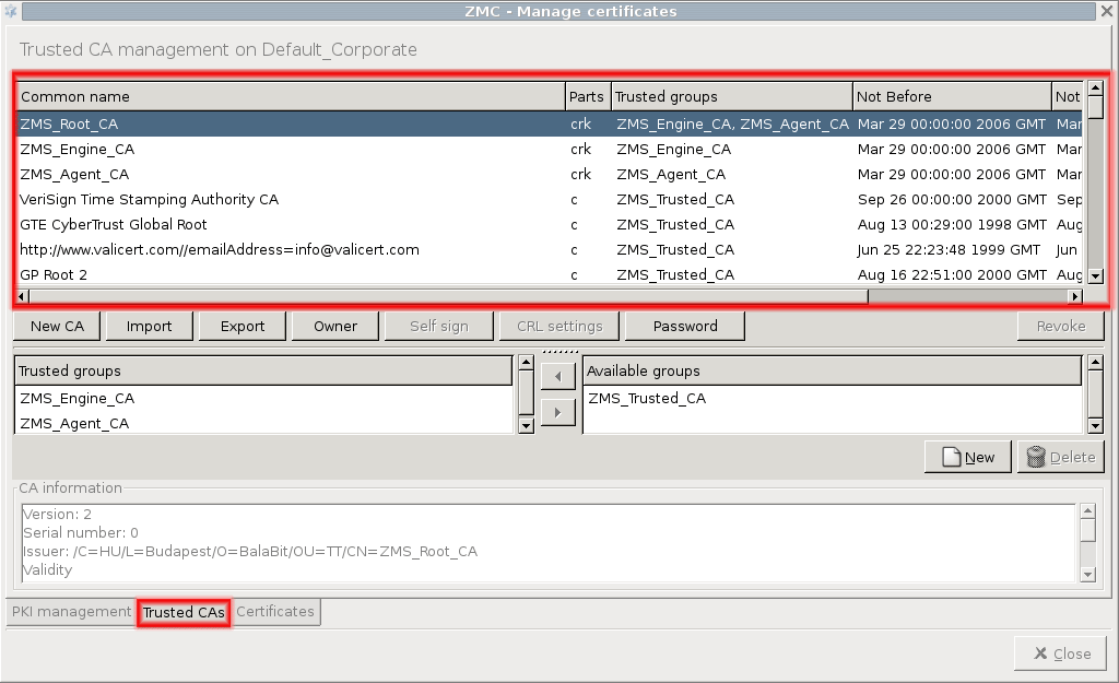
The command bar contains various operations that can be performed with CAs. Some of them require a CA to be selected from the information window, in this case the given operation will be performed on the CA selected.
: Create a new local Certificate Authority. For details, see Procedure 11.3.7.2, Creating a new CA.
: Import a CA certificate from a PEM, DER, or PKCS12 formatted file.
: Export the certificate of the selected CA into file in PEM, DER, or PKCS12 format. The PKCS12 format is only available for internal CAs.
-
: A CA available on a site can be made available on all sites managed by MS by clicking this button and checking the checkbox. This has the same effect as checking the corresponding checkbox when creating a new CA.
Warning This operation cannot be reversed or undone.
-
: Self-sign the CSR of the selected local CA. Only certificates not yet signed by a CA can be self-signed.
Note Local root CAs could be created by self-singing a so far unsigned CSR of a Trusted CA.
-
: Set the parameters for refreshing the CRL of the selected external CA. Parameters to set are:
: At what time should the retrieval of the CRL be started.
-
: How often should the CRL be retrieved.
By setting the to 00:00 and the to 04:00, the CRL will be downloaded every four hours, starting from midnight.
-
: Location of the CRL to be retrieved. The CRL can be downloaded through HTTP.
Note It is very important to set the refresh URL, otherwise the validity of the certificates issued by the CA cannot be reliably verified. The CRL should be downloaded and automatically distributed regularly.
: File format of the CRL to be downloaded (PEM or DER).
: Change the password of the selected local CA.
: Revoke the certificate of the selected local CA that was signed by another local CA. Self-signed CA certificates cannot be revoked this way. For details, see Procedure 11.3.8.3, Revoking a certificate.
: Delete the selected certificate. For details, see Procedure 11.3.8.4, Deleting certificates.
11.3.7.2. Procedure – Creating a new CA
-
Navigate to the tab of the , and click on .
-
Enter the required parameters for the subject of the new CA's certificate. It is recommended to give a descriptive common name to the CA, to make it easier to remember its function.
-
Select the encryption algorithm and key length to be used.
Tip The key of the CA certificate should be longer than the ones that will be issued by the CA, for example, if the CA will be used to sign certificates having 1024 bit keys, the key of the CA certificate should be at least 2048 bit long.
-
Select the signature digest (hash) method to be used.
Tip Use of the SHA1 algorithm is recommended, as it is considered to be more secure and not significantly more computation intensive.
Provide a password to protect the private key of the CA. This is required so that only authorized users can sign certificates.
-
Click on , and specify for which purposes will the certificate be used.
Note The use of extensions is optional.
-
When creating a local root CA, check the checkbox and specify the validity period of the certificate.
Tip If the CA is to be available on every site managed, do not forget to check the appropriate checkbox when creating the New CA.
Warning Making a CA certificate available on all sites cannot be reversed, that is, once CA has been made available on all sites, later it cannot be limited to a single site.
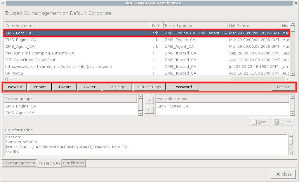
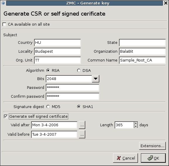
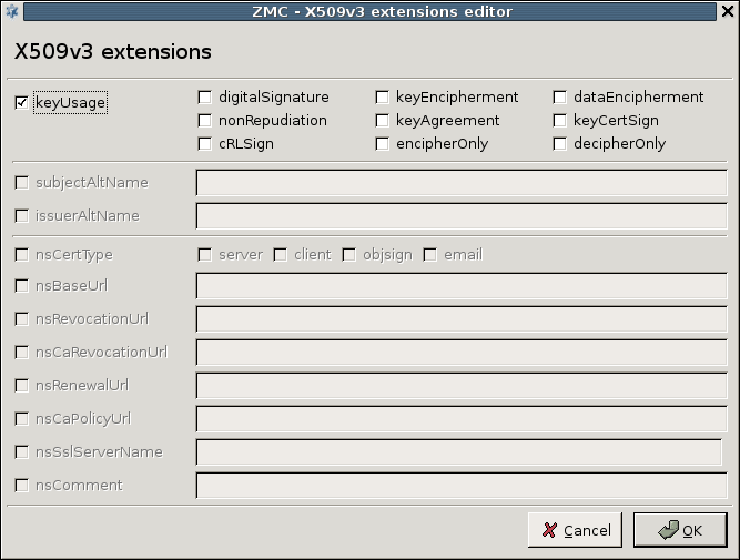
The are displayed on the right side of the panel, while the groups that the selected CA is member of are displayed on the left. Adding or removing a CA to a group can be performed using the arrow-shaped icons in the middle.
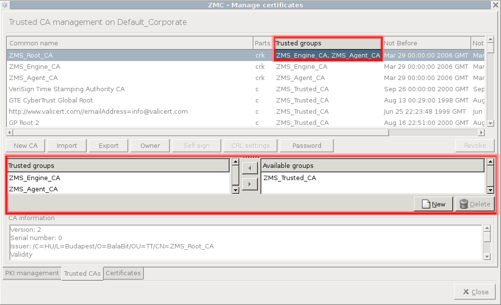
11.3.7.4. Procedure – Signing CA certificates with external CAs
If you want to use an external CA to sign the certificate of a local CA, complete the following steps.
Generate a private-public keypair and an associated CSR using the button of the tab.
Export this CSR into a file using the button.
Have the CSR signed.
-
If the CA approves your identity and signs the certificate, it to the PKI system of MS.
Note Be sure to select the appropriate entity (that is, to import the signed certificate to the proper CSR) and to check the option.
The certificate entity can now be distributed and used on your machines.
All non-CA certificates available on the selected site can be managed here. Importing and exporting certificates is also possible.
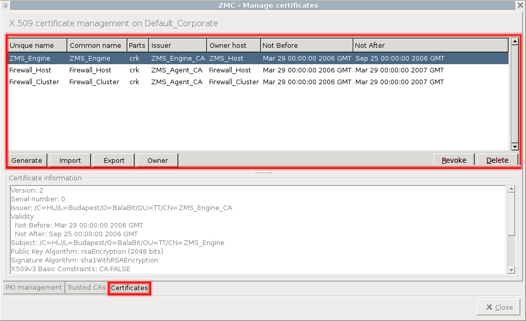
The upper section of the panel displays the list of available certificates, along with the following information on each:
of the certificate entity.
of the certificate.
available from the certificate entity. For external certificates usually only their certificate (c) is available; for internal CAs their private key (k) and the CSR (r) can be available as well.
: The CA that has signed the certificate. This field is empty if the CSR is not yet signed.
: Determines which host can use the private key.
: The certificate's period of validity.
The command bar contains buttons that can be used to perform various operations on the certificates available on the site. Some of them require a certificate to be selected from the information window, in this case the given operation will be performed on the selected certificate.
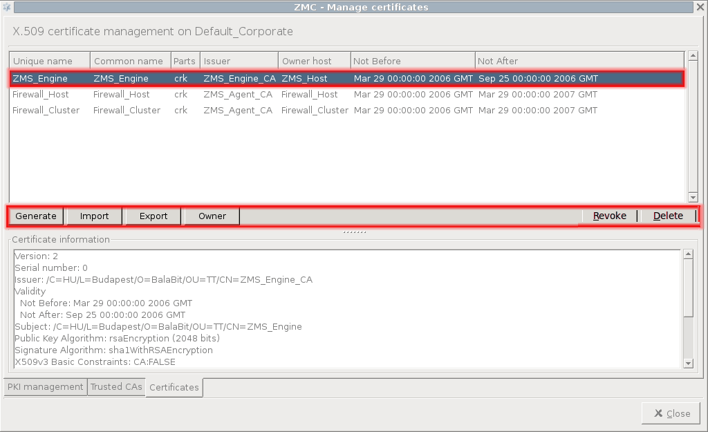
: Generate a new CSR.
: Import a certificate (or a part of it) from a PEM, DER, or PKCS12 formatted file.
: Export the selected certificate (or a part of it) into file in PEM, DER, or PKCS12 format.
: The owner site of the certificate can be specified here, or the certificate can be made available on all sites managed by MS. This latter operation cannot be undone.
: Revoke the selected certificate. This operation requires the password of the issuer CA.
11.3.8.2. Procedure – Creating certificates
To create a certificate, complete the following steps.
From the menu, select and click .
-
Click , and fill the Generate CSR form.
Enter a Unique name that will identify the object containing the certificate and the key in MS.
Select the host that will be the owner of the certificate from the combobox.
If you want the certificate to be available on every site that is managed in MS, select .
Fill the Subject section of the request as appropriate. Into the field, enter only a two-letter id (for example, US). Enter a name for the certificate into the field.
-
Select the length of the key (1024, 2048, or 4096 bit).
Note Longer keys are more secure, but the time needed to process key signing and verification operations (required for using encrypted connections) increases exponentially with the length of the key used. By default, 2048 bit is used.
MC 1.0 can create only RSA keys, generating DSA keys is not supported.
Warning If the certificates/keys have to be used on machines running older versions of the Windows operating system, using only 1024 bit long keys might be required, since these Windows versions typically do not support longer keys.
Select the method (SHA256 or SHA512) to be used for generating the Signature digest (hash).
-
By clicking on , the various purposes of the certificate can be specified. For details on X.509v3 extensions, see Appendix C, Further readings.
After specifying all the required options, click .
-
Navigate to the tab, and in the navigation window select the local CA to be used to sign the request (for example,
MS_Agent_CAfor transfer agents, and so on).
-
Click on . A window will be displayed listing the submitted but not yet signed CSRs. The list displays the distinguished name of the CSRs, this includes the various Subject fields (Country, locality, common name, and so on) specified when generating the request.
Set the validity period (Valid after/Valid before dates) of the certificate. A pop-up calendar is available through the button. Alternatively, after setting the Valid after date, the field can be used to specify the length of the validity in days, automatically updating the Valid before field.
By clicking on , various X.509 extensions can be specified. These extensions can be used to ensure in filters that only certificates used for their intended purpose are accepted.
Enter the password of the CA required for issuing new certificates, and click .
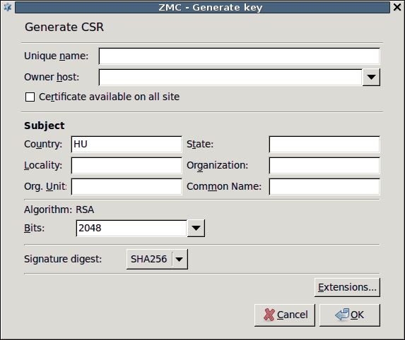
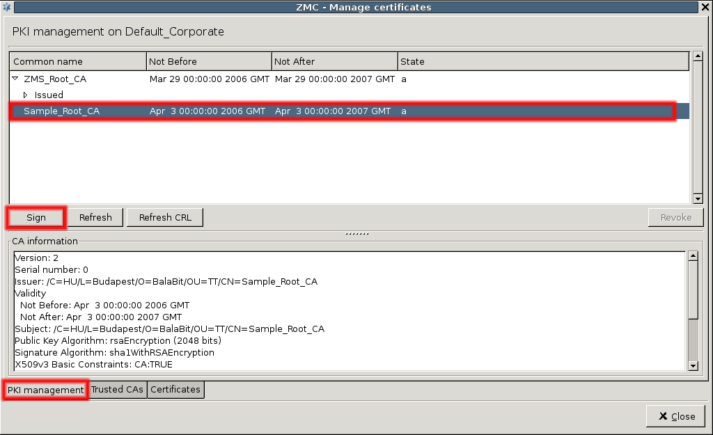
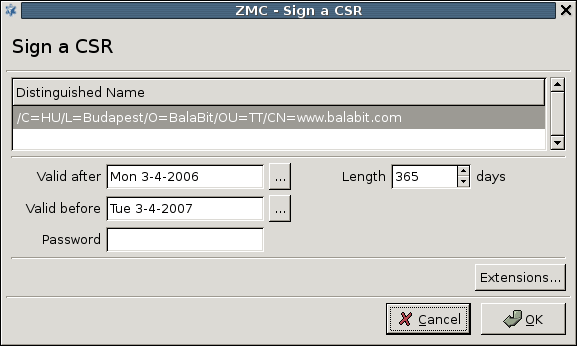
11.3.8.3. Procedure – Revoking a certificate
To revoke a certificate, complete the following steps.
-
Select the certificate to be revoked.
-
For general certificates, click on either on the or the tab. CA certificates can be revoked from either the or the tab.
Note Only certificates signed by local CAs can be revoked.
Self-signed CA certificates cannot be revoked.
-
Enter the password of the issuer CA. If the private key associated to the certificate is to be deleted as well, check the checkbox. Click .
Tip If the private key of a certificate has been compromised, the private key should be revoked along with the certificate. Generally it is recommended to generate new keys each time a certificate is refreshed.
On the tab, the certificate will now appear in the list of its CA. On the tab, the dates of its validity will disappear, and the section will indicate that only the CSR (r) and (if it has not been revoked) its private key (k) is available.
The CRL of the issuer CA is refreshed automatically.
The revocation will be effective on the PNS hosts only when their CRL information is updated from MS. If MS is not configured to perform distribution automatically (or the update should be made available immediately), it can be performed manually through the menu item.
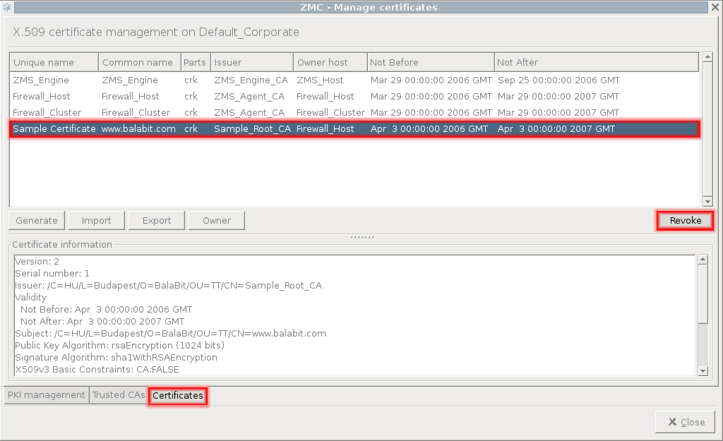
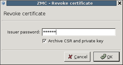
11.3.8.4. Procedure – Deleting certificates
To export a certificate from the MS PKI, complete the following steps.
Revoke the the certificate you want to delete. For details, see Procedure 11.3.8.3, Revoking a certificate.
On the tab, select the certificate you want to delete and click .
From the main menu, select .
11.3.8.5. Procedure – Exporting certificates
To export a certificate from the MS PKI, complete the following steps.
Select the CA certificate or certificate to be exported on the or tab, respectively.
Click on .
-
Select the directory to save the file to, specify the file format to be used, and enter the filename, and click .
Note File extension is NOT added automatically to the filename.
The file will be saved to the local machine, that is, the one that is running MC.
-
Depending on the file format to be used, the part(s) to be saved can be specified. Naturally, only the parts that are available can be selected (for example, only the CSR or the key if the certificate has not been signed yet).
If the private key is exported as well, the key can be password-protected by specifying an .
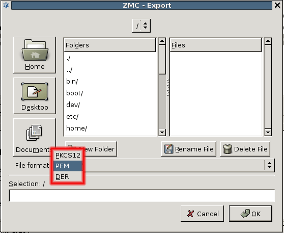
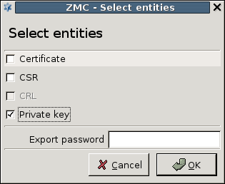
11.3.8.6. Procedure – Importing certificates
-
Click on on the tab for importing CA certificates, or on the tab for normal certificates.
Note If the parts contained in the file are to be imported to be added to an existing certificate entity, select the given certificate entity before clicking on . This function is useful for importing certificates signed by external CAs.
Specify the file format to be used, and select the file to be imported.
-
Select the part(s) to be imported.
-
There are two ways to handle the data imported from the file: creating a new entity or appending them to an existing one.
Creating a new entity: Select the radio button, enter a Unique name and select the Owner host of the object. This method is useful especially for importing the certificates of external CAs.
Import parts to an existing certificate: It is possible to import the part(s) contained in the file into an existing certificate entity (that is, the one that was selected before clicking on the button). This method should be used when importing your certificates that were signed by an external CA, so the certificate is imported to the entity containing the private key and the CSR. Select the radio button.
Enter the if the private key is imported and the key has been password-protected.
Check the checkbox if needed.
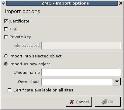
11.3.8.7. Procedure – Signing your certificates with external CAs
If you have an external CA to sign your certificates and you want to manage these certificates in PNS, complete the following steps.
| Tip |
|---|
The Import and Export operations provide a convenient way to handle certificates signed by external CAs. For details, see Procedure 11.3.8.6, Importing certificates and Procedure 11.3.8.5, Exporting certificates. |
Generate a private-public keypair and an associated CSR using the button of the tab.
Export this CSR into a file using the button.
Have the CSR signed.
-
If the CA approves your identity and signs the certificate, it to the PKI system of MS.
Note Be sure to select the appropriate entity (that is, to import the signed certificate to the proper CSR) and to check the option.
The certificate can now be distributed and used on your machines.
11.3.8.8. Procedure – Monitoring licenses and certificates
Purpose:
The MS and PNS hosts monitor the validity of product licenses and certificates, and automatically send alert e-mails if any of them will expire soon. By default, the host sends e-mail alert to the administrator e-mail address specified during the installation 14 days before the expiry.
The validity of the available product licenses (MS, PNS, CF, AS, NOD32) is checked once every day on each host that is managed from MS. The validity of CA certificates and certificates is checked only on the MS host.
To configure the details of the certificate monitoring, complete the following steps.
Steps:
Add a new component to the host to edit the
/etc/zmsagent/expiration.conffile. For details on editing a file using the component, see Procedure 8.1.1, Configure services with the Text editor plugin.Configure the address of the mailserver, and the e-mail address of the recipients as needed. For details on the available parameters, see the manual page of expiration.conf.
Commit and upload your changes.
Execute the /etc/cron.daily/expiration_check.py --test-mail command to send a test e-mail.
A cluster is a group of computers dedicated to performing the same task. These computers (referred to as nodes of the cluster) use the same (or very similar) configuration files (policies, iptables, and so on). The goal of clustering in general is to integrate the resources of two or more devices (that could otherwise function separately) together for backup, high availability or load sharing purposes. In other words, clusters are computer systems in which more than one computer shares the tasks or the load in the network. A PNS cluster usually consists of a group of firewall hosts that maintain the same overall security policy and share the same configuration settings.
Basically there are two types of clusters. In a fail-over cluster if a machine breaks down, a spare computer is started immediately to ensure that the service provided by the computers is continuously available (see Section 12.2.1, Fail-Over clusters). Load balancing clusters are used when the traffic generated by the provided service is more what a single computer can handle (see Section 12.2.2, Load balance clusters).
Clustering provides the following advantages:
ensures continuous service and decreased downtime,
contributes to High Availability (HA),
assists to satisfy service level agreements, and
improves load balance in the system.
The following terms will be frequently used in this chapter:
- Host
A single computer offering services to the clients.
- Node
A single computer belonging to a cluster, offering services to the clients exactly with the same functionality as the other nodes in the cluster.
- Cluster
A (logical and physical) group of computers offering services to the clients. Clusters are made up of nodes. In MS, the nodes of a cluster are handled together: from the administration point of view a cluster behaves similarly to a single host.
The aim of fail-over clustering is to ensure that the service is accessible even if one of the servers breaks down (for example, because of a hardware error). In fail-over clusters only one of the nodes is functioning and carries the whole traffic, the other(s) only monitor the active node. In case of system failure resulting in a loss of service, the service is started on the other node in the system. In other words, if the active component dies the other node takes over all the services.
| Note |
|---|
The service is failed over to the other component only in case of hardware failure, if you stop PNS no backup mechanism is initiated automatically. |
Monitoring between the cluster nodes is realized with the help of Heartbeat messages. For more information, see Section 12.5, Heartbeat.
The transfer of services can be realized using one of the following methods:
Transferring the Service IP address
Transferring IP and MAC address
Sending RIP messages
In this case the servers use a virtual (alias) IP address (called Service IP), clients access the service provided by the servers by targeting this Service IP. The Service IP is carried by the active node only. If the node providing the service (that is, the master node) fails, the Service IP is taken over by the slave node. As all clients send requests towards the Service IP, they are not aware of which device that address belongs to, and do not notice any difference when a takeover occurs.
When the cluster relocates the Service IP to the other node it sends a gratuitous arp request message to the whole network informing the clients that the Service IP belongs now to a different node. As a result, the clients flush their arp cache and record the new arp address of the Service IP. (A gratuitous ARP request is an AddressResolutionProtocol request packet where the source and destination IP are both set to the IP of the machine issuing the packet and the destination MAC is the broadcast address ff:ff:ff:ff:ff:ff. Ordinarily, no reply packet will occur.)
Service IP takeover is the most frequently used takeover method for PNS clusters.
| Note |
|---|
Some clients may not take over the new Service IP address until the next automatic arp cache flush, which causes certain delay in Service IP transfers in the system. The problem is that the arp cache is refreshed relatively rarely, and it is not possible to notify the clients that they should update their arp cache. |
In some systems, usually in large networks it is disadvantageous to modify IP address – Media Access Control (MAC) pairs, because certain routers do not refresh their arp cache, causing problems in the network traffic. In this case the fail-over functionality is realized by taking over the Media Access Control (MAC) address.
In such systems, all nodes use the same fix IP and hardware MAC address in the network and the nodes are differentiated by the state of the servicing interface. The master (active) node has the interface in up state while the slave nodes' interfaces are kept down. If the service is failed over to the other node, the interfaces get into up state. Client requests are serviced by the node having the interface in up state.
Transferring MAC address is beneficial if the resources need to be relocated very quickly.
| Warning |
|---|
Multiple interfaces with the same IP or MAC address connecting to a network as a result of a failed takeover can destabilize the network. Consequently, it is important to monitor the takeover process and to completely remove (for example, power off) the failed server from the network. This can be accomplished by using a STONITH device. See Section 12.5, Heartbeat for details. |
In this case no Service IP is used. All nodes have their own IP addresses and the routing information is sent through Routing Information Protocol (RIP) messages using different metrics.
| Note |
|---|
RIP metrics are ranging from 1 to 6. You have to define the metrics for each node according to your network environment. |
Routers in the network select the destination components based on these metrics. They send the traffic to the node with lower metrics value. If a node fails, it is sufficient to remove it from the network and traffic is transferred through the other nodes without any further interaction.
| Note |
|---|
|
The router mediating the client requests towards the firewall has to support RIP message transfer. Desktop clients and common server machines usually do not support RIP messages. PNS uses the Sendrip software for this purpose. |
In load balance configurations, all nodes of a cluster provide services simultaneously to distribute system load and enhance the overall quality of service. Clients access the service by targeting a single domain name, without knowing how many servers provide the actual service.
The amount of traffic handled by one node is determined by some logic. Currently PNS does not provide any built-in tool for defining such criteria, therefore an external device has to be used. This can be either the DNS server, or a dedicated load balancer.
DNS load balancing is based on the native behavior of name resolution, that is when the DNS server resolves a domain name into more than one IP addresses the client chooses one IP from the answers using the round robin algorithm. Though for the decision the client disregards the actual load of the server, the solution results in balanced load in the system. In this case the firewalls offer a non-transparent service, because the client targets the firewall itself.
It is possible to use load balancer devices to distribute the traffic between the nodes. In this case the balancing method can be configured on the load balancer device. Of course, load balancing solutions also offer a native fail-over solution. If one node stops working and the load balancing device notices that, it does not direct traffic to that node until it is functioning again.
Load balancer devices offer load balancing only from the point of the client, it has no influence on the proxy at the other side of the firewall — in such case line load balancing must be solved on the firewall. If you need to share a load from several directions (physical networks), separate load balancer devices are needed in each direction.
| Note |
|---|
|
The firewall has to have a separate load balancer device towards all connected interfaces. From proxying point of view, all connections, and in case of multi-channel protocols, like FTP, all channels have to go through the same node. |
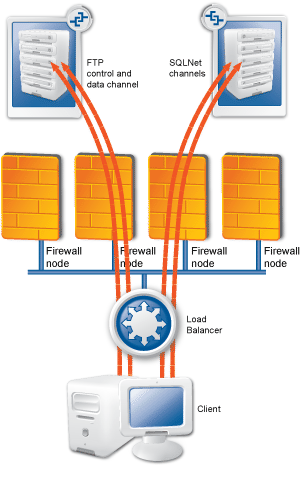
The third party device added to the system must be able to direct multi-channel protocols through the same node.
A simple load-balancing solution is to assign a multicast MAC address to the Service IP. In this case the clients target the Service IP, and a hub or switch before the firewall hosts forwards all requests to the multicast MAC address, resulting in all nodes of the cluster receiving all packets sent to the Service IP. The IP addresses of the clients are distributed between the nodes using some logic (for example, one nodes serves only clients with odd, the other one clients with even IP addresses), and the packet filter of each node is configured to accept only the packets of the clients they are responsible for.
| Note |
|---|
It is important that if in such a scenario one of the nodes fails, the remaining nodes have to take over the clients served by the failed node. This can be accomplished for example by using resources. |
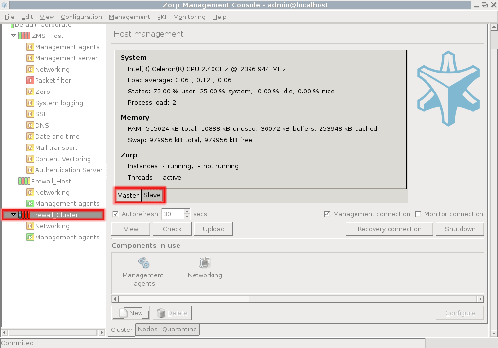
The nodes of a cluster have identical configurations, only a few parameters are different. When configuring clusters, all nodes are configured simultaneously, as if the cluster were a single host. For each parameter that is different on the nodes of the cluster, links have to be used. It is also possible to link to a property of the cluster, in this case the link will be evaluated to a different value on each node. That way when the configuration is uploaded, each node will receive a configuration file containing the values relevant for the node.
Any parameter can be used as a property; usually parameters like the IP addresses of the interfaces are properties. New properties can be added any time to the cluster, not only during the initial configuration.
Naturally, not all links used in a cluster have to be links to cluster properties, regular links can be used as well. However, keep in mind that links to cluster properties are resolved to the corresponding property of the particular node. For example, a link to the Hostname property of a cluster is resolved on each node to the hostname of the node (for example, to node_1 on the first node, and so on).
| Note |
|---|
The PKI of the site considers the cluster to be a single host, there is no difference between the individual nodes. |
As a result of using properties, adding new nodes to a cluster is very easy, since only the properties have to be filled with values for the new node.
When uploading configuration changes, or viewing and checking configurations, you can select on which node the operation should be performed.
Controlling a service (for example, restarting/reloading) is possible on all nodes simultaneously, or only on the nodes specified in the selection window.
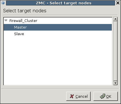
Status indicator icons on clusters behave identically to hosts, except that a blue led indicates a partial status, meaning that the nodes of the cluster are not all in the same state (for example, the configuration was not successfully uploaded to all nodes).
When configuring rules for PNS clusters, use links to the interfaces. From the clients' point of view this makes no difference, as the clients do not target the IP of the PNS host.
For non-transparent services, the rule must use the Service IP (that is, a link to the Service IP), because that is where the clients will send their requests to.
When configuring a new cluster, there are several distinct steps that have to be completed. An overview of the general procedure is presented below. The main tasks are to create and configure the cluster nodes; to configure Heartbeat (required only for fail-over clusters and certain load-balancing solutions); and finally to create the policies, services on the cluster.
First the new cluster has to be created in MC. This can be either a cluster created from scratch, or (optionally) an existing host can be converted into a cluster. In both cases the initial cluster has only a single node, the additional nodes have to be added (and bootstrapped) manually. Bootstrapping a cluster node is very similar to bootstrapping a regular host. It is important to create properties for the parameters that are different on each node (for example, hostname, IP address, and so on) and use links during configuration when referring to these properties.
In case of fail-over and multicast load-balancing clusters, the component also has to be installed and configured. For load-balancing clusters where the load-balancing is performed by an external device (that is, a load balancer, DNS server, and so on), this external device also has to be configured. Configuring has two main steps, first the communication between the nodes has to be configured, then the Heartbeat resources that are taken over when a node fails have to be created (see Section 12.5, Heartbeat for details).
After completing the above procedure, the cluster-specific configuration of the system is finished — later steps can be performed identically to managing the policies of regular hosts.
The individual steps of the above procedure are described in the following sections in detail.
| Note |
|---|
The procedures in the subsequent sections describe the configuration of a PNS firewall cluster. Although this is the most common scenario, other components of the PNS Application Level Gateway System (for example, CF, AS) can also be clustered. |
| Warning |
|---|
When creating a PNS cluster, the MS managing the cluster must be on a dedicated machine, or on a PNS host that is not part of the cluster. MS cannot be clustered. |
12.4.1. Procedure – Creating a new cluster (bootstrapping a cluster)
To create and bootstrap a new cluster, complete the following steps:
| Note |
|---|
As an alternative to creating a cluster and bootstrapping its first node, an existing PNS host can also be converted into a cluster. For details, see Procedure 12.4.4, Converting a host to a cluster. |
Select the site that will include the new cluster from the configuration tree, and click on in the menu.
-
Select the and click on to start bootstrapping the first node of the cluster.(Bootstrapping cluster nodes is very similar to bootstrapping individual PNS hosts. For more information see Chapter 4, Registering new hosts.)
-
Provide a name for the cluster (for example,
Demo_cluster), as well as an , an and a (for example,Demo_cluster_node1) for the first node of the cluster. The node will accept connections from the MS agents on the specified pair. The rest of the bootstrapping process is identical to bootstrapping a normal PNS host, that is, create a certificate for the cluster, supply a one-time-password, and so on. For more information see Chapter 4, Registering new hosts.
-
After bootstrapping the first node of the cluster, complete the following procedures as needed:
Add additional nodes as required. For details, see Procedure 12.4.3, Adding a new node to a PNS cluster.
Adding new properties to the cluster. For details, see Procedure 12.4.2, Adding new properties to clusters.
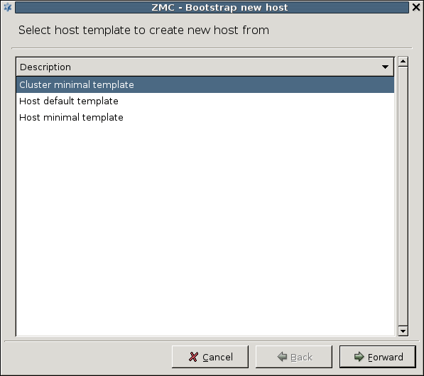
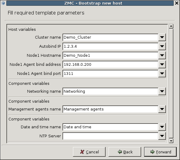
12.4.2. Procedure – Adding new properties to clusters
As properties have to be used for all parameters that are different on each node, it is recommended to create all properties before adding the additional hosts to the cluster. Naturally, this is not required; properties can be defined any time. To add a new property to the cluster, complete the procedure below.
-
Click the button on the tab of the cluster to define a new property.
-
Enter a name for the new property, and select the type and subtype of the property.
The possible property subtypes are the following.
ip_address
port
ip_netmask
interface_name
hostname
You can set initial values for the properties as well.
The new property is added to all nodes automatically. (Properties can be manipulated both in and view.)
Set the value of the new property for all nodes separately by clicking the button.
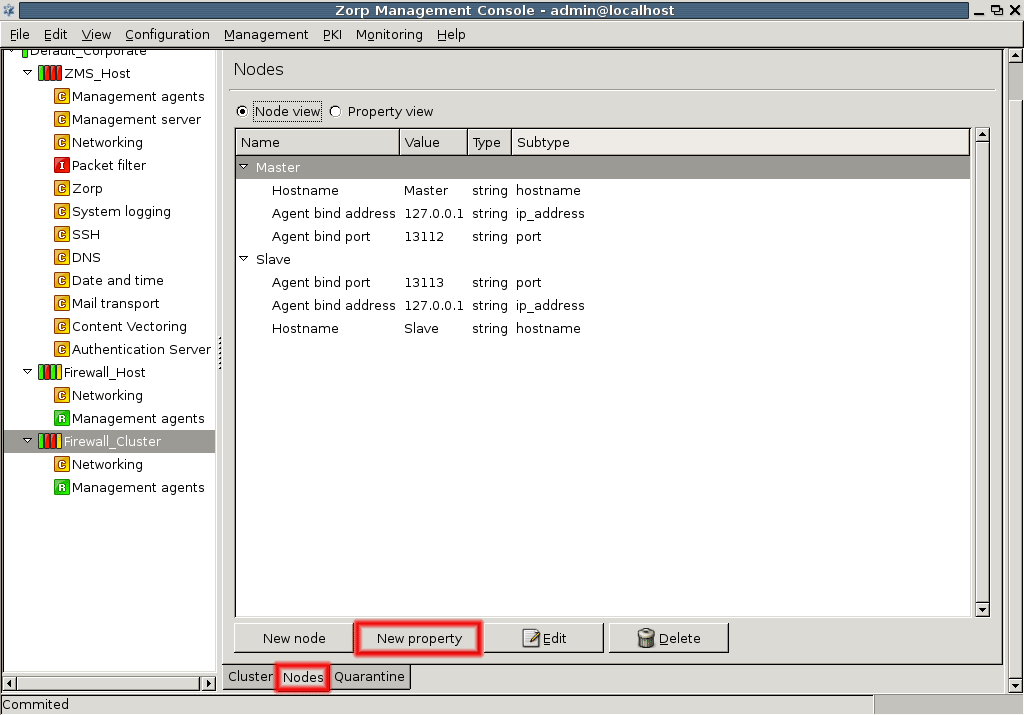
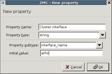
12.4.3. Procedure – Adding a new node to a PNS cluster
-
Click the button on the tab of the cluster.
-
Set the properties of the new node in the appearing window. Enter hostname, agent bind address and bind port, and any other properties that have been added to the cluster.
Tip You are recommended to use the default port setting.
Do not forget to check the checkbox to automatically commit the changes and connect to the new node. If this checkbox is not selected when the new node is created, the configuration must be committed into the MS database manually. Also, the node cannot be connected automatically, only through a recovery connection (see Procedure 13.3.4, Configuring recovery connections).
If you create a fail-over cluster, usually the second node is configured to be the slave node.
-
Enter the one-time password.
-
Click the button if the password is correct to build up the connection.
A standalone text informs you again of the background procedures. Save the output with the button so that it can be analyzed later if needed. The text window should look similar to this.
Note You can check the status and connections of cluster nodes by selecting the item in the menu.
After bootstrapping a cluster and adding new properties you can freely add the necessary components and configure the nodes according to your needs. Basically, the configuration procedure is similar to a PNS host configuration. When configuring clusters using the component, proceed to Section 12.5.3, Configuring Heartbeat.
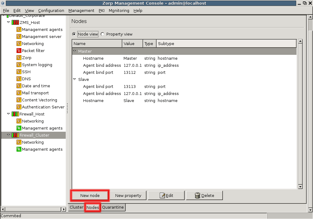
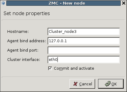
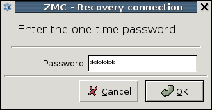
12.4.4. Procedure – Converting a host to a cluster
Existing PNS hosts can also be converted into a cluster relatively easily. In this case the PNS host will be converted into a node of the new cluster.
| Warning |
|---|
When a host is converted into a cluster, it retains all parameters that were set explicitely on the host. These parameters have to be replaced with links manually if needed. Typically, properties have to be created and links used for the |
Select the host you want to convert to a cluster.
Select the in the menu.
Enter a name for the cluster.
In several cluster solutions (for example, in fail-over and multicast load-balancing clusters) the nodes in the cluster must monitor each other to detect if one of the nodes fails.
is a tool monitoring the status of the nodes in a cluster. The components of the nodes send keep alive messages to the other node(s). When the node stops sending heartbeat packets it is assumed to be dead, and any services (resources) it was providing are taken over by the other node(s). For this functionality, you need to define the master and slave nodes, set encryption for the communication between the nodes, and also establish and configure a dedicated interface for the communication.
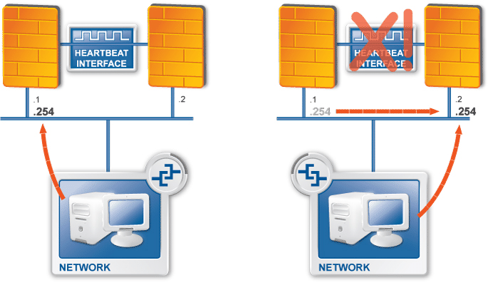
| Note |
|---|
|
In order to use Heartbeat, the You are recommended to encrypt the Heartbeat signals even if you are using a dedicated interface. |
Heartbeat packets can be transferred through a serial null modem cable and / or Ethernet network, for example in case of geographically separated cluster nodes. If Ethernet is used, the heartbeat signals are UDP packets targeting a broadcast address.
Heartbeat instances are installed on all nodes. Both the master (active) and the slave (passive) nodes send heartbeat packets as a kind of keep-alive message across a dedicated interface. These messages enable the monitoring and, if needed, the takeover of each others' resources. When heartbeat packets are no longer received, the node is assumed to be dead, and any services (resources) it was providing are failed over to the other node.
| Note |
|---|
|
Unfortunately it is possible that the active node fails only partially, that is, although it stops sending heartbeat messages, it still replies to ARP request or and retains the Service IP. Such situation results in two hosts — seemingly both functioning — owning the same IP on the LAN. To avoid such situation the death of the node has to be ensured by the integration of a STONITH (Shoot the Other Node In The Head) device, which practically turns off the power on the master node if it is dead. It is also possible to install a hardware watchdog into the nodes of a cluster. A hardware watchdog is a small device that periodically receives some kind of signal (for example the heartbeat messages) from the computer — either from the kernel, or from a specific application. If the computer stops sending these signals, it is assumed to be dead, and the watchdog reboots the node. |
| Tip |
|---|
Create a dedicated network for heartbeat messages using two Network Interface Cards (NIC) and a crossover Ethernet cable connecting them. |
Another important task of is that it manages the Resources of the cluster. A resource can be anything that is available on a node of the cluster and is relevant to the service it provides: it can be an IP address (for example, the Service IP of a fail-over cluster), a software running on the nodes (for example, PNS), and so on. Actually these resources are what is taken over when a node fails. Heartbeat manages the resources through resource scripts — regular shell script files that can start and stop the resource on the node (for example, bring an interface into up/down state), and can return status information about the resource (for example, indicate whether the interface is in up or down state). How to configure heartbeat resources is described in Procedure 12.5.4, Configuring Heartbeat resources.
To configure the Heartbeat component, add it to the cluster first.
| Note |
|---|
The component can monitor multiple nodes, however, the MC component currently (version 3.4) supports only two nodes. It is possible to create and manage clusters containing three or more nodes in PNS, but the configuration file has to be edited and managed manually in this case. |
12.5.3.1. Procedure – Configure Heartbeat
Select the cluster in the configuration tree and click the button below the subwindow on the tab to add the
Heartbeatcomponent.-
Choose the template and then change the component name, if needed.
The
Heartbeatcomponent appears in the configuration tree. -
Define the master and slave hosts in the field of the Heartbeat main window. Each node must have a unique hostname.
-
Define encryption method for the Heartbeat messages.
The default encryption is sha1, but md5 and CRC are also possible.
Tip It is recommended to use the default sha1 encryption.
-
Click the button and give a password.
-
Now the communication channel used to transfer heartbeat messages between the nodes has to be configured. The following steps describe how to configure an Ethernet interface for this purpose. This involves using resources as well; the use of resources is described in Procedure 12.5.4, Configuring Heartbeat resources in detail.
Note When using a serial interface to transfer the heartbeat messages between the two machines, a serial null-modem cable has to be used. It is recommended to use the highest possible communication speed (baud rate). For further information see the documentation of Heartbeat at http://www.linux-ha.org/ConfiguringHeartbeat.
Go to the
Networkingcomponent of the cluster, tab. Create a new interface, for example,eth1for HA purposes using the button. -
Link the cluster HA IP address in the field using the link icon. Enter the broadcast address as well.
Set and the fields, if no defaults are provided.
-
Go to the
Heartbeatcomponent of the cluster and click at the field. Click and select the newly created interface as the HA interface for Heartbeat using the link icon or the drop down list.Note Heartbeat can use two or more interfaces to avoid false takeovers when the HA interface of a node breaks down. If multiple HA interface are configured, the slave node becomes active only if all HA interfaces stop transmitting heartbeat messages.
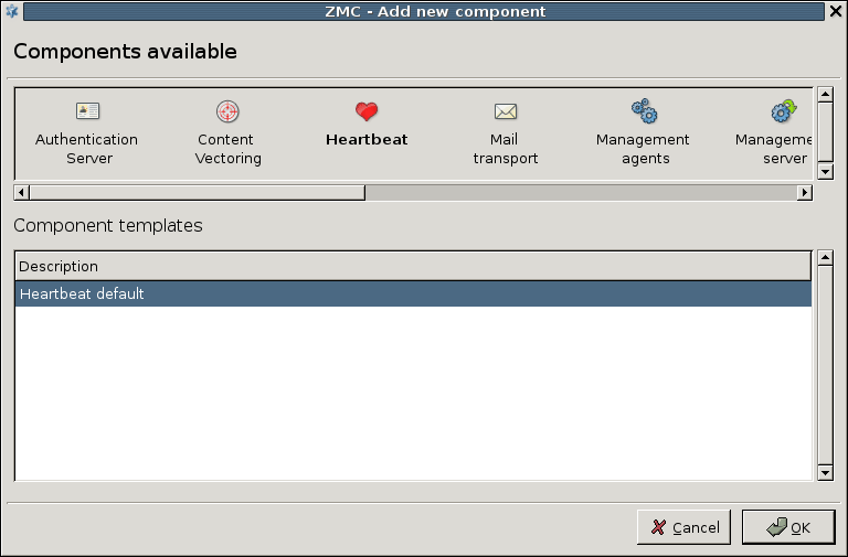
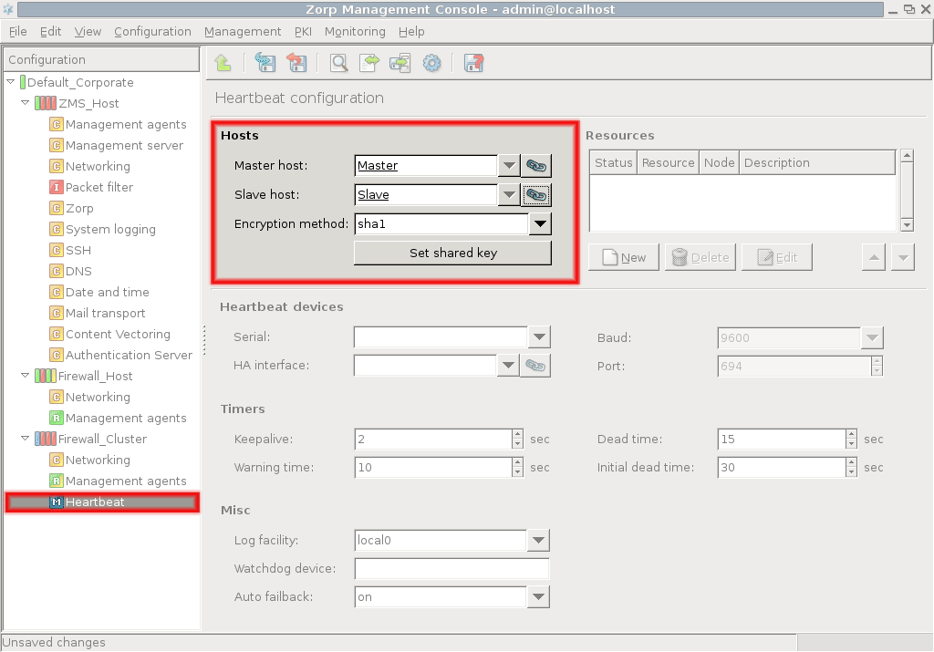
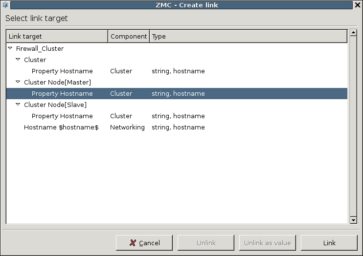
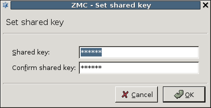
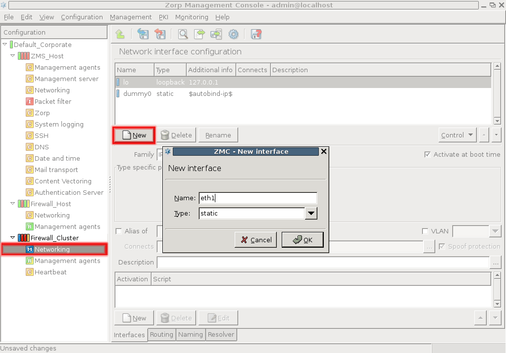
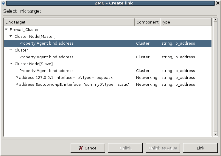
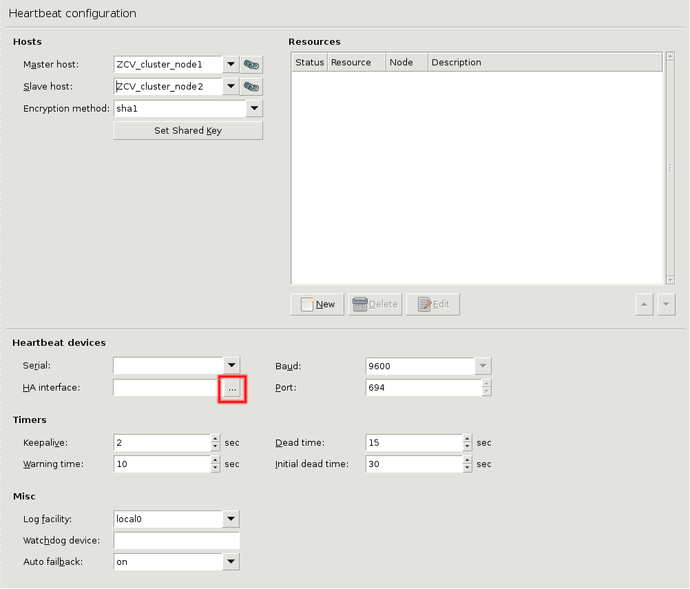
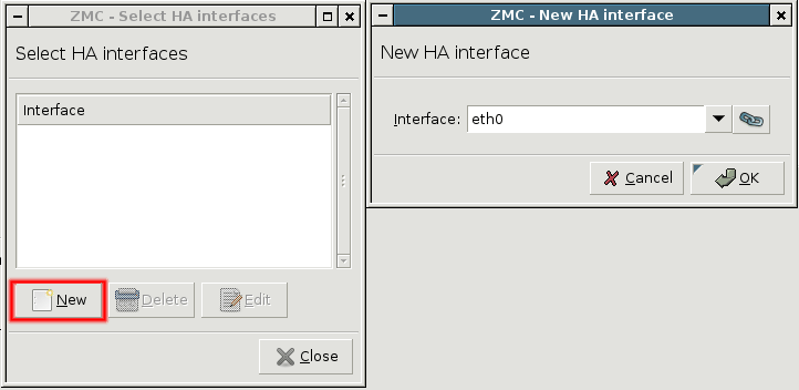
12.5.3.2. Procedure – Configure additional Heartbeat parameters
-
Set timers for Heartbeat in the section.
You can define the following timers. Give all the values in seconds.
- keepalive
The interval in seconds between subsequent Heartbeat signals.
- warning time
The interval in seconds after which the slave node gives warning of the dead master node.
- dead time
The interval in seconds after which the node is assumed to be dead.
- initial dead time
First deadtime after system reboot in seconds.
Tip It may take a while in some machines to have a fully functional network after a reboot. It is recommended to set the dead time twice the warning time, and the initial deadtime twice the dead time. For example, if the warning time is 20 seconds, the optimal dead time is 40 seconds and the optimal initial dead time is 80 seconds.
-
Set other Heartbeat options in the subwindow.
You can select log target, watchdog device and decide about service re-acquiry in case of master node recovery.
- log facility
This option determines the target device for logging.
- watchdog
-
This option determines which watchdog device is used, if any. For example, /dev/watchdog.
Watchdogs can monitor the heartbeat messages of a node and reboot the node if it fails.
- nice fallback
-
This option prevents the master node from re-acquiring cluster resources after a failover in case the master node gets functional again. Enabling
nice_failbackcan cause problems in certain situations. Suppose there is a two-node cluster with a master (Node_A) and a slave (Node_B) node. IfNode_Afails,Node_Bacquires its resources and uses a STONITH device to power off theNode_A. WhenNode_Arecovers, the resources remain onNode_Bifnice_failbackis enabled. However, if nowNode_Bseems to fail,Node_Acan power offNode_Bonly if two STONITH devices are intalled to the system (one to power offNode_A, one to power offNode_B).Tip It is recommended to enable
nice_failback, but after a takeover restore the original master-slave node hierarchy at the earliest possible time (for example, during the next maintenance break).
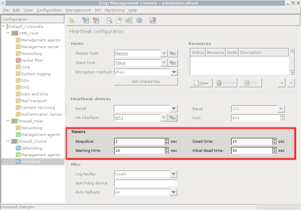
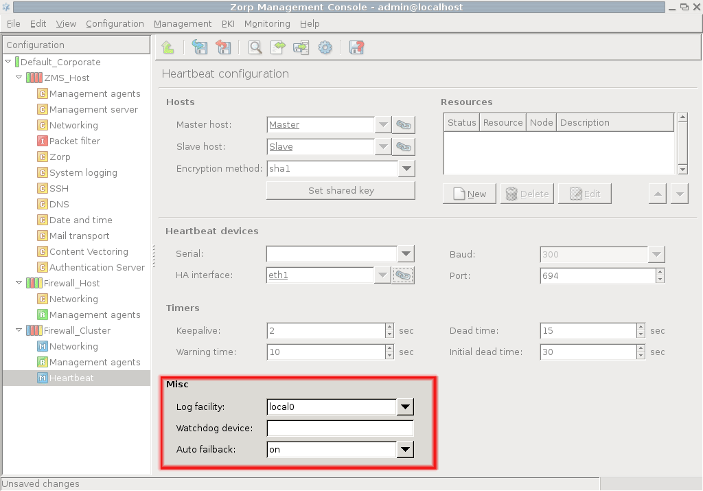
12.5.4. Procedure – Configuring Heartbeat resources
Configuring Heartbeat resources has two main steps: creating the resource scripts and adding these resources to the component in MC. The general procedure is as follows.
-
Create a resource script, or modify an existing one. Heartbeat resource scripts have to be placed into the
/etc/ha.d/resource.d/directory — this directory contains a number of resource script samples that cover the most commonly used scripts. You only have to edit the parameters of the selected script.The resource scripts installed by default are described in Step 3.
-
Navigate to the component of the cluster. Resources can be managed in the section of the panel. Click on to add a new resource.
-
Enter a name for the resource — this has to be the name of the resource script.
The following resource scripts are available by default (see the actual scripts in the
/etc/ha.d/resource.ddirectory of the nodes for details):-
: Adds/removes an alias IP address (that is, the Service IP).
Note If only an IP address is specified as the resource name, it is automatically considered as an
IPaddrresource. : Manages the preferred source address associated with packets which originate on the localhost and are routed through the default route.
: Sends an e-mail to the system administrator whenever a takeover occurs.
: An alternative to the resource to send gratuitous arp for an IP address on a given interface without adding the address to that interface. It should be used if for some reason you want to send gratuitous arp for addresses managed by on an additional interface.
-
The node on which the resource is active by default can be selected using the radio buttons.
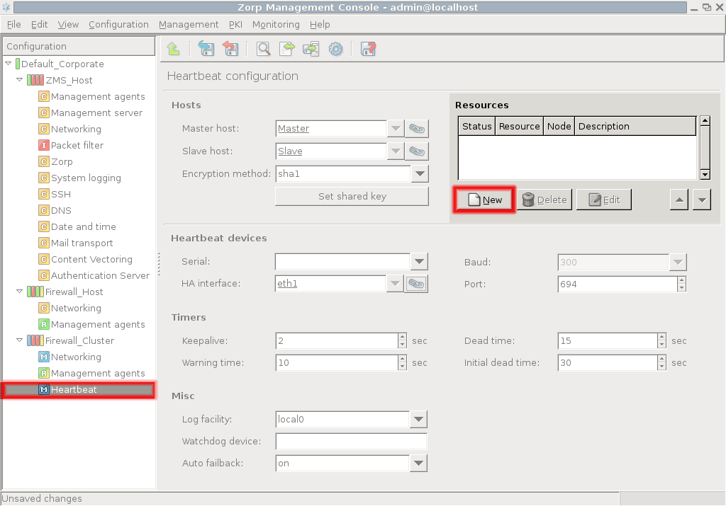
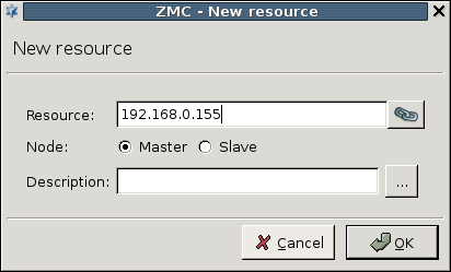
12.5.5. Procedure – Configuring a Service IP address
The following example describes how to create an alias network interface and configure it as the Service IP of a cluster.
Navigate to the component of the cluster and click on in the section.
Enter a name for the alias interface (for example,
eth1:1). For further information on alias interfaces see Section 5.1.2, Configuring virtual networks and alias interfaces.-
Enter the
IP address,Netmask,Broadcast address, and so on parameters into the respective fields. TheIP addressspecified here will be the Service IP of the cluster, to be accessible by the clients.Warning Be sure to uncheck the checkbox.
-
Create a new resource by clicking the button in the section of the component.
Enter the Service IP address. It is recommended to use linking to the IP address of the alias interface created in the previous steps. Also select the node where the resource is active using the and radio buttons.
The Management Server (MS) is the central component of the PNS Management System. It governs all configuration settings, manages the firewall services through agents and handles database functions.
MS provides a tool for the complete control and maintenance of the PNS firewalls entirely. You can create new firewall configurations, and navigate them to the firewall nodes. MS stores these configurations in an associated XML database making them available for later administrative operations.
Communication with the PNS firewall software is realized the Transfer Agent responsible for accepting and executing configuration commands.
For further information on MS and the basic architecture, see Chapter 2, Concepts of the PNS Gateway solution.
To modify firewall settings you need to carry out the following procedure regardless of which component is configured.
-
Make the necessary changes in a component's configuration.
Changes can be undone with the option as long as they are not committed to the MS database
-
Commit the new configuration to the MS database.
The MS host stores the modified information in its XML database. Remember to commit the changes before leaving the component.
You can always view the new configuration and compare it with the current firewall configuration with the help of the and options, respectively.
-
Upload the configuration to propagate the changes from the MS database down to the firewalls(s).
During this process the MS converts the configuration data to the proper configuration file format and sends them to the transfer agents on the firewall nodes.
-
Reload the altered configuration or restart the corresponding services to activate the changes.
Typically, reloads or restarts are performed after finishing all configuration tasks with the various service components.
For more details, see Chapter 3, Managing PNS hosts.
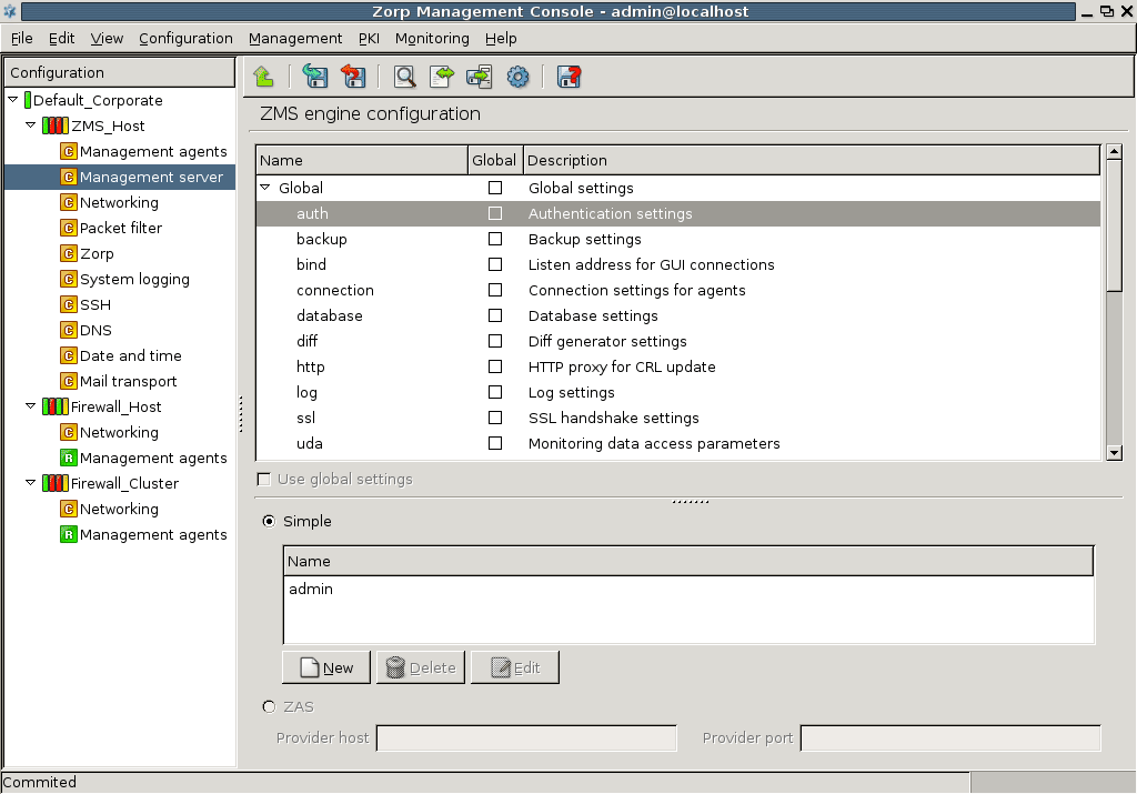
MS configuration is realized by setting the appropriate parameters of the component. The following parameters can be configured.
| Parameter name | Description | |
|---|---|---|
auth
|
Authentication settings | For handling user data and passwords |
backup
|
Backup settings | For configuring backup |
bind
|
Listen address for GUI connections | For setting connection between MS and MC |
connection
|
Connection settings for agents | For defining connection parameters |
database
|
Database settings | For defining saving to disk |
diff
|
DIFF generator settings | For commanding configuration check |
http
|
http proxy for CRL settings | For defining proxy address |
log
|
Log settings | For configuring logging parameters |
ssl
|
SSL handshake settings | For configuring SSL settings for MS and agent connection |
Table 13.1. MS configuration parameters
By using global settings it is possible to apply default values to the parameter set.
| Note |
|---|
You are recommended to use the global settings when no special configurations are needed. |
Different configurations are possible for the following subsystems:
configuration database,
key management,
and transfer engine.
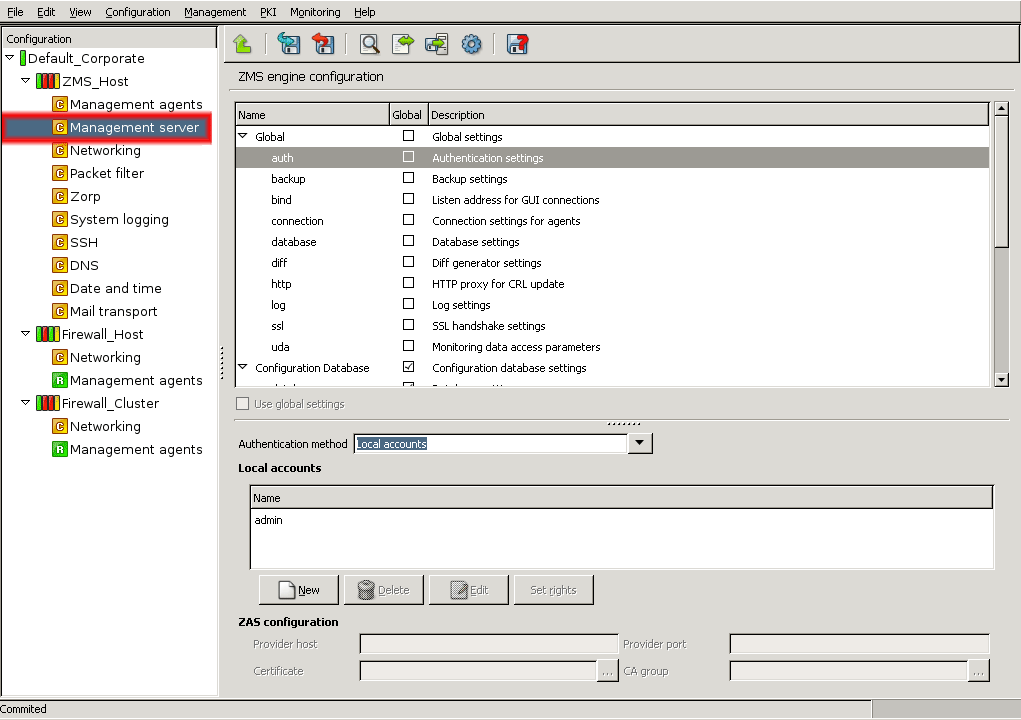
With the Authentication settings (auth) parameter you can configure access to MS. Users are listed in the main textbox. You can perform the following tasks:
| Note |
|---|
Only the |
13.1.1.1. Procedure – Add new users
Navigate to the component of the host running MS, and select the parameter from parameters.
Click to add new users to the system.
-
Enter username and password in the opening window.
Confirm password.
Click , commit and upload your changes, and reload the component.
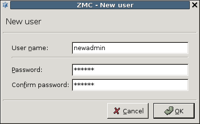
13.1.1.2. Procedure – Deleting users
| Note |
|---|
Only the |
Navigate to the component of the host running MS, and select the parameter from parameters.
Select the user you want to delete and click .
Commit and upload your changes, and reload the component.
13.1.1.3. Procedure – Changing passwords
| Note |
|---|
Only the |
Navigate to the component of the host running MS, and select the parameter from parameters.
Select the username whose password you want to change.
Click .
Enter the current password and a new password in the opening window.
Confirm the new password.
-
Click , commit and upload your changes, and reload the component.
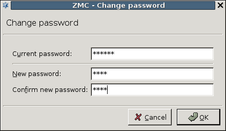
In order to help configuration auditing and the general process of PNS administration, MC users can now have different access rights. That way different administrators can have different responsibilities — PKI management, log analysis, PNS configuration, and so on.
| Note |
|---|
Only the |
13.1.1.4.1. Procedure – Editing user privileges
| Note |
|---|
Only the |
Navigate to the component of the host running MS, and select the parameter from parameters.
Select the username whose privileges you want to edit.
-
Click .
Note To change the password of the user, click .
-
Select the privileges you want to grant to the user. A user can have none, any, or all of the following privileges:
Modify configuration: Modify and commit the configuration of the hosts. The user can perform any configuration change, and commit them to the MS database, but cannot activate the changes or control any services or components.
Control services: Start, stop, reload, or restart any instance, service, or component. This right is required also to upload configuration changes to the hosts.
PKI: Manage the public key infrastructure of PNS: generate, sign, import and export certificates, CAs, and so on.
Log view: View the logs of the hosts.
To create a 'read-only' user account for auditing purposes, do not select any privileges.
To create a user account with full administrator rights, select every privilege.
-
Click , commit and upload your changes, and reload the component.
Users connecting to MS using MC must authenticate themselves. The following authentication methods are available:
Local accounts: MS stores the usernames and passwords in a local database. This is the default authentication method.
Local accounts and AS authentication: MS stores the usernames locally, but receives the authenticates the users against a AS instance. All users successfully authenticating against AS and having a local account can connect to MS.
13.1.1.5.1. Procedure – Modifying authentication settings
Navigate to the component of the host running MS, and select the parameter from parameters.
Select the desired authentication method in the field.
-
If you selected , you have to configure access to AS in the section.
Note Using these authentication methods requires an already configured AS instance. See Chapter 15, Connection authentication and authorization for details on using and configuring AS.
Enter the IP address or the hostname of the Authentication Server into the field. By default, AS accepts connections on port
1317.Select the certificate that MS will use to authenticate itself from the field.
Select the CA group that contains the CA that issued the certificate of AS from the field. MS will use this group to verify the certificate of AS.
-
If you are running more than one authentication backends (more than one AS instances), create a new router in the MC component that will direct the authentication requests coming from MS to the appropriate AS instance.
Add a new condition to the router, and enter
Authentication-Peerinto the field, andzmsinto the value field.For details on configuring AS routers, see Section 15.3.1.2, Configuring routers.
Note MS sends also the username in the authentication requests. This can be used to direct authentication requests to different AS instances based on the username.
Click , commit and upload your changes, and reload the component.
With the Backup settings (backup) parameter you can define the automatic MS database backup method. You can enable automatic backup and then determine the base time for the first backup and also the interval between all subsequent backup processes. Additionally, you can define how many database backup copies are stored. Alternatively, you can create scripts to handle the backup tasks.
Backups are stored in the /var/lib/zms/backup directory of the MS host. The name of the backup file is zms-backup-<timestamp>.tar.gz
| Warning |
|---|
If you do not enable automatic backup you have to save the database manually, otherwise all database information might get lost. |
13.1.2.1. Procedure – Configuring automatic MS database backups
Select .
-
Enter for the first backup.
Use hours:minutes format, for example, 08:00.
-
Define the between the backups.
Use hours:minutes format, for example, 00:30. In most cases it is sufficient to backup once or twice daily.
-
Select the number in to define how many backup records are stored.
The default value is 10, meaning that only the last 10 database backups are available. The allowed values are ranging from 1 to 100.
The more backups you store, the more space it reserves. Since one record is only 1-2 MB you can keep 20-50 records if needed without overloading the system.
-
(OPTIONAL)
Tick and give the path of the desired script if you want to use a special script for the backup.
Tip Using an external script is a good way to copy the backups to an external host, for example, a backup server.
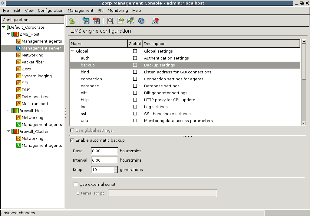
13.1.2.2. Procedure – Restoring a MS database backup
The following steps describe how to restore an earlier MS database.
| Warning |
|---|
Restoring an earlier database will delete the current database, including the configuration of every host, as well as any certificates stored in the PKI system. Any modification and configuration change performed since the backup was created will be lost. |
Copy the database backup archive file to the MS host.
As root, issue the /usr/share/zms/zms-restore.sh <backup-file-to-restore> command.
Follow the on-screen instructions of the script.
Login to MS using MC. If you have reinstalled MS, use the username and password you have provided during the reinstallation.
If the restored database has to be upgraded, MC displays a list of the components to be upgraded. Click .
Select . Note that key distribution will fail on every host except on the MS host. This is normal.
Upload the configuration of the MS host.
Restart at least the Management Server component on the MS host. This will terminate your MC session.
Relogin with MC and check your restored configuration.
Upload and restart any component as needed. You may also need to redistribute the certificates.
With the Listen address for GUI connections (bind) parameter you can configure the connection between the MS and the MC. You need to give the bind address and the bind port to define where to listen for the GUI connection.
13.1.3.1. Procedure – Configuring the bind address and port for MS-MC connections
-
Provide the bind address. You have the following alternatives to define the bind address.
-
Enter IP address manually.
-
Select the needed IP address from the drop-down menu.
The menu shows the available IP interface addresses.
Note Note that in case the IP address changes for some reason, you need to modify this data manually since changes are not propagated automatically.
-
Use variables.
MS resolves variables during configuration generation (view, check and upload processes). For more information on using variables, see Chapter 3, Managing PNS hosts.
-
Create link to an IP address.
Note You are recommended to give the address this way so that future address changes will have no effects on the operability of the connection.
1. Procedure – Using linking for the IP address
Click the link icon.
Select the link target in the opening window.
-
Click .
If you click and options you delete the existing links. If you choose it ceases the link connection totally, meaning that the link field is left empty while deletes the link but leaves the target IP address in the field which will then behave as a manually added address.
-
-
Provide bind port. You can define bind ports similarly to bind address.
Enter port number manually.
Use variables.
Create link to a port
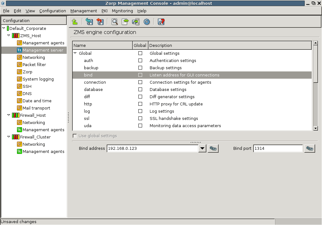
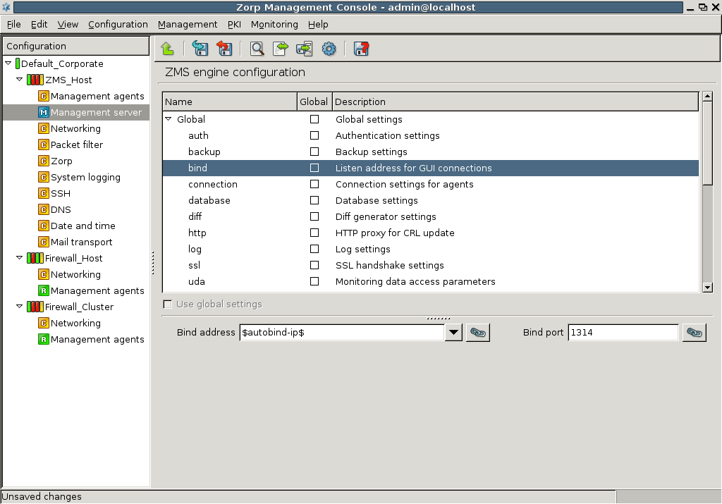
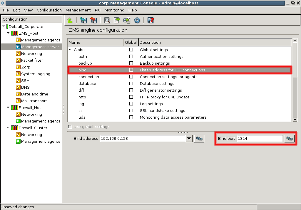
13.1.4. Procedure – Configuring MS and agent connections
With the Connection settings for agents (connection) parameter you can determine which bind address and port you want to use for the connection between MS and the agents. You can set awaiting time and the number of retry can be given too.
Defining bind address and ports for the agents is done similarly to defining address and ports between MS and MC. By default, the MS initiates the connection, but if you give MS port and address for the connection parameter at the agent's side, the agent can also establish the connection. In that case, the same port and address should be set for this parameter too.
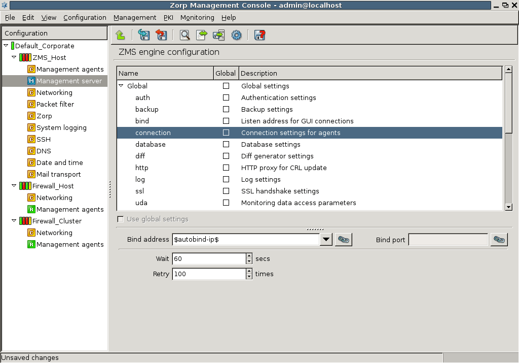
Define bind address. The bind address can be defined manually, selected from the available interface addresses, or using variables or links (these possibilities are described in Section 13.1.3, Configuring the connection between MS and MC in detail).
-
Set waiting time and the number of retries. These configure how long MS waits for live communication with the agents and in case the connection cannot be set up, how many times MS attempts to connect to the agents. Use the and fields.
Note If you give too low value for waiting time or too high for retry you may overload the system and cause unnecessary network traffic. Default values are optimal in most cases.
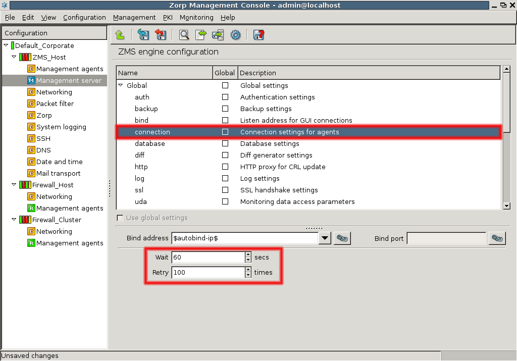
13.1.5. Procedure – Configuring MS database save
With the Database settings (database) parameter you can set how frequently the MS database is saved to disk in both idle and active modes.
-
Select the appropriate number in the field to determine the interval between two database backups when the MS XML database is not in use, that is, no changes are committed.
Give values in seconds. The default value is 10. All values are allowed.
-
Select the appropriate number in the field to determine the interval between two database backups when the MS XML database is used and changes are committed.
Give values in seconds. The default value is 120. All values are allowed.
Note Since the XML database is constantly updated when the MS is in use you are recommended to keep busy threshold value not too low to decrease system load. On the other hand, when choosing high threshold values it is important to bear in mind that during any system breakdown or power outage data might get lost because the database is kept only in the memory and not saved to disk.
By default, MS sends warnings a week before a certificate expires. You can modify this value here.
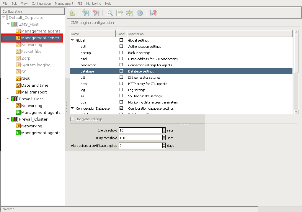
With the DIFF generator settings (diff) parameter you can give the command to be executed when comparing the database on the host with the MS configurations with the button.
Enter the full path of the command.
The default command is /usr/bin/diff. You can use special commands, parameters or your own scripts for the configuration check, if needed.
With the http proxy for CRL settings (http) parameter you can give the URL of the proxy you want to use to retrieve the CRL from.
Enter the URL according to your proxy settings, for example, http://proxy.example.com:3128/.
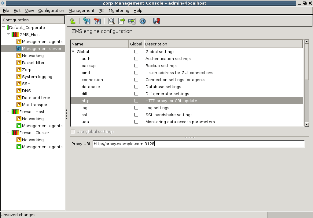
13.1.8. Procedure – Set logging level
With the Log settings (log) parameter you can determine which type of messages should be logged. You can apply logtags to enable advanced message filtering and also to determine where the messages should be logged to.
-
Select the desired level of logging.
The default value is level 3 which means that all important events are logged but no detailed debug information. The higher the value the more information is logged. The levels from 0 to 10 are allowed.
-
(OPTIONAL)
Give log specification if you want to fine-tune for which logtags what level of messages are logged, for example,
core.debug: 2, session.error:8,*. accounting:5.. -
(OPTIONAL)
Tick if you want to log to syslog, otherwise the messages are logged to the standard output (STDOUT).
Tip Logging on the console might be useful during troubleshooting.
-
(OPTIONAL)
Tick if you want to log the logtags as well.
Tip This is beneficial if you need to search and analyse the log messages, but takes up more disk space.
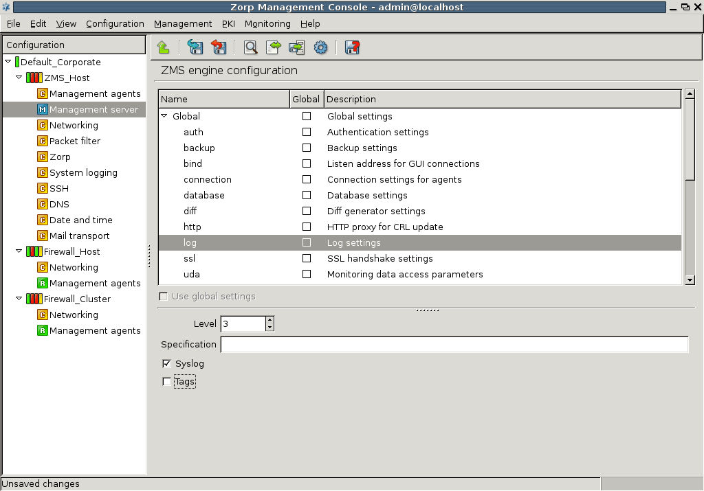
13.1.9. Procedure – Configuring SSL handshake parameters
With the SSL handshake settings (SSL) parameter the certificate verification parameter and other handshake-related information can be set.
-
Select verification level in the field to decide how many levels are verified in the certificate hierarchy.
Values from 0 to 100 are allowed.
-
Choose or with the radio buttons.
Note You are recommended to use the PKI groups configuration.
-
In settings select the certificate entity for the MS host.
For example: MS_engine. If you open the Certificate selector window you can see the unique identifier of the MS host and also certificate information, such as version, serial number, issue date and validity period, algorithms and keys. This information is useful when selecting which certificate to use.
-
Select agents validator CA group.
For example: MS_Host_CA. If you open the CA group selector window you can define the CA group which is used to verify the certificate of the agents during the handshake. Data is available on CA group name, certificate name and certificate information for the selected CA groups.
OR
-
In settings enter manually the following data.
full path of the file where the private key is stored,
certificate,
CA directory identifying the directory where the CA certificate entities are stored,
-
and CRL directory giving the place of the CRLs corresponding to the CA
screenshot
-
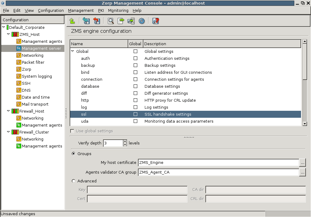
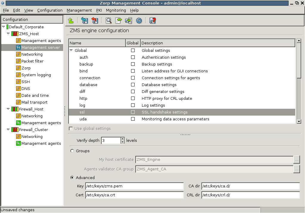
Agent configuration, similarly to MS configuration, is realized by setting the appropriate parameters. The following parameters can be configured for the agents.
| Parameter name | Description | |
|---|---|---|
connection
|
Connection settings for agents | For defining connection parameters |
engine
|
Engines to connect | For configuring connection to engines |
log
|
Log settings | For configuring logging parameters |
ssl
|
SSL handshake settings | For configuring SSL settings for MS and agent connection |
Table 13.2. Agent configuration parameters.
By using global settings it is possible to apply default values to the parameter set.
| Note |
|---|
You are recommended to use the global settings when no special configurations are needed. |
With the Connection settings (connection) parameter you can set which bind address and port you want to use for the connection between the agent and the MS. The agent receives or initiates the connection from / to the MS engine using this address. You can set waiting time and the number of retries as well. Note that you are recommended to allow MS to establish the connection towards the agent. The configuration process is identical to the one described in Section 13.1.3, Configuring the connection between MS and MC.
For further information, see Section 13.2.1, Configuring connections for agents and Section 13.3, Managing connections.
With the Engines to connect (engine) parameter you can configure to which engine the agent connects to. Generally, it is the engine that connects to the agent but if you set this parameter the agent initiates the connection based on these settings.
| Note |
|---|
You are recommended to leave this parameter empty and allow the MS engine to establish the connection towards the agents. |
13.2.3. Procedure – Configuring logging for agents
With the Log settings (log) parameter you can determine which type of messages should be logged at the agent's side. You can apply logtags to enable advanced message filtering and also determine where the messages should be logged to.
-
Select the desired level of logging.
The default value is level 3 which means that all important events are logged but no detailed debug information. The higher the value the more information is logged. The allowed levels are from 0 to 10.
-
(OPTIONAL)
Give log specification if you want to fine-tune for which logtags which level of messages are logged, for example,
core.debug: 2, session.error: 8,*. accounting:5.. -
(OPTIONAL) Tick if you want to log to syslog, otherwise the messages are logged to the standard output (STDOUT).
Tip Logging on the console might be useful during troubleshooting.
-
(OPTIONAL)
Tick if you want to log the logtags as well.
Tip This is beneficial if you need to search and analyze the log messages, but takes up more disk space.
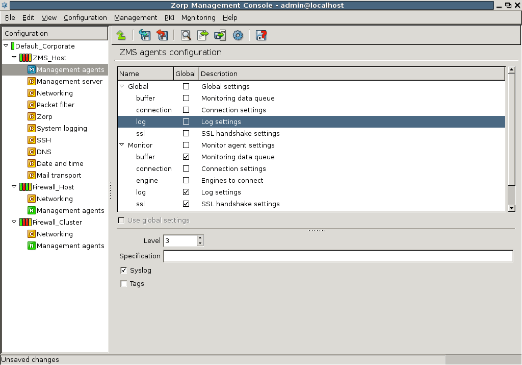
13.2.4. Procedure – Configuring SSL handshake parameters for agents
With the SSL handshake settings (SSL) parameter you can set certificate verification parameters for the agent and other handshake-related information to be used between the agent and the MS.
-
Select verification level in the field to decide how many levels are verified in the certificate hierarchy.
Values from 0 to 100 are allowed.
-
Choose or with the radio buttons.
Note You are recommended to use the PKI groups configuration.
-
In settings select the certificate entity for the agent.
For example: MS_engine.
If you open the window you can see the unique identifier of the MS host and also certificate information, such as version, serial number, issue date and validity period, algorithms and keys.
Tip This information is useful when selecting which certificate to use.
-
Select engine validator CA group.
For example: MS_engine_CA.
If you open the window you can define the CA group which is used to verify the certificate of the agents during the handshake. Data is available on CA group name, certificate name and certificate information for the selected CA groups.
OR
-
In settings enter manually the following data.
full path of the file where the private key is stored,
certificate,
CA directory identifying the directory where the CA certificate entities are stored,
-
and CRL directory giving the place of the CRLs corresponding to the CA
screenshot
-
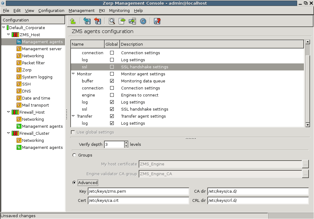
MS communicates with the PNS firewall software through agents. The zms-transfer-agent communicates using TCP port 1311.
The initial connection between the firewall and MS needs manual set up, but all subsequent communication channels are established automatically. By default, the MS host initiates the connection towards the agents but agents can also establish the communication if configured to do so. You can administer the connections through the MS host main workspace and with the help of the menu.
Give MS port and address for the Connection settings for agents (connection) parameter, if you want that the agents initiate the connection towards the MS using this port and address. The same port and address should be given at the agent's side. If you give no values the default connection setup is carried out, that is, the MS connects to the agents using the given port and address.
For further information, see chapter Section 13.2.1, Configuring connections for agents.
13.3.3. Procedure – Administering connections
Go to the main workspace of the MS host.
-
Select .
-
Query connection status by choosing option from the menu.
The field shows the outcome of the previous connect or disconnect operation.
-
(OPTIONAL)
Stop or Start the communication by selecting the connection and clicking or .
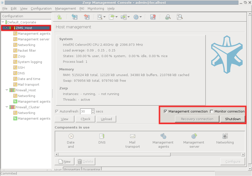
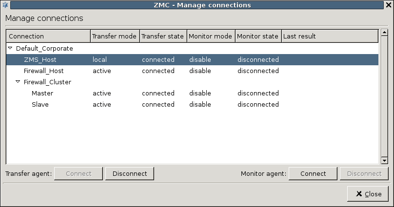
13.3.4. Procedure – Configuring recovery connections
You have to configure a recovery connection in the following cases:
Connecting a new machine (firewall node) to the MS without bootstrapping (to set up the initial connection between MS and the PNS firewall).
Installing a new firewall machine to replace a previous one and configuring it based on MS data.
The authentication in this case is done using a One-Time-Password (OTP) instead of certificates. After successful authentication, the MS receives the configuration data of the agent together with the necessary PKI information (certificate, key and CRL). All further authentication procedures will use this data. After the agent is restarted, the MS initiates the reconnection. The administration can be done as normal afterwards.
| Note |
|---|
The agent needs to be in OTP mode to be able to receive the connection. |
Login to the PNS host that you want to reconnect to MS.
Reconfigure the zms-transfer-agent with the following terminal command:dpkg-reconfigure zms-transfer-agent-dynamic
Enter a One-Time-Password (OTP) that the host will use to connect to MS into the window displayed. Enter a password, and store it temporarily for later use.
Login to your Management Server using MC.
-
Select the host that needs the recovery connection in MC, and click .
-
Enter the same One-Time-Password (OTP) that you set during the installation on the host.
Upload and reload the configuration of every component of the host.
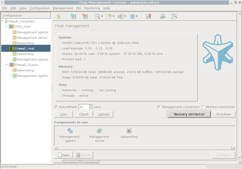
The XML database in the MS is functionally divided into two parts and stores two basic types of information.
-
Predefined information
For example: proxies, packet filtering parameters or add-ons. This information is provided by but other definitions can also be added freely.
Configuration settings of your sites, hosts or components. Practically, the settings that you have created in the MC. The configuration files are generated on the basis of this data.
MS loads the database information from the /var/lib/zms library and places it in the appropriate part of the XML database. During database save MS carries out the reverse process: takes the data from the XML database and saves it in the appropriate file and folder of the library.
The /var/lib/zms is library is composed of the following folders and XML files.
-
zms_userdatabase.xmlincluding your configuration settings created in the MC except for PKI information
-
zms_keymngt.xmlincluding all PKI information and related user settings.
-
configdbfolderstoring templates, databases, definitions necessary for the MS such as built-in proxies or other settings provided by (configuration settings are excluded).
Note Do not change the files in this folder because during upgrade it is automatically overwritten. Necessary modifications should be stored in the
configdb-userfolder. -
configdb-userfoldercontaining your additional settings and templates for the MS in separate XML files
(These files are modified versions of the
configdb/zms_database.xmlfile). This data is not deleted during upgrade. -
keymngtfoldercontaining certificate entities (certificate, key and CRL files generated by PKI).
Note Do not modify this folder.
-
backupfolderstoring by default the backup of the XML files and folders.
For further information, see chapter Section 13.1.2, Configuring backup.
Virus, spam and other types of content filtering services are nowadays essential components of security solutions both in home and in production environments. Spam, viruses, trojans, malicious scripts pose a significant threat to the users through e-mails, downloadable files, or even simple webpages. Firewalls are a logical location for content filtering, as all traffic must travel across the firewall, and usually this is the earliest point where the incoming traffic can be examined and interacted with. CF provides an integrated framework to manage the various available content vectoring components using a single, uniform interface.
The sections of this chapter provide an in-depth description of CF. For a basic overview of the CF framework, content vectoring and a list of the supported modules, see Section 2.1.6, The concept of the CF framework.
Content vectoring is basically the act of inspecting the transmitted data (downloaded by a web browser, sent over SMTP, and so on) to detect and reject unwanted content. Depending on the environment and the circumstances, unwanted content can mean viruses, ad- or malware, spam e-mails, client-side scripts (that is, Java, JavaScript, and so on), or simply websites containing information not permitted for the users (such as adult sites, and so on).
| Note |
|---|
Content vectoring may seem to be similar to application level protocol inspection performed by PNS proxies. However, it is essentially different: the proxies only analyze the elements of the protocol, not the transferred data itself. |
The main types of content filtering are summarized below.
Virus filtering: The most classical and well-known form of content vectoring is virus filtering: examining the files being transferred to verify that they do not contain any software that may harm the user's computer or infrastructure. Most virus filtering engines also detect adware and trojan programs. If a virus is detected, often it is possible to remove the virus (disinfect the file) without any side-effect.
Spam filtering: Spam filtering examines e-mails (usually in the SMTP traffic) to delete unwanted advertisements, viruses spreading through e-mails, and so on.
Disabling client-side scripts in HTML: Client-side scripting is a popular method for decreasing the load of webservers. It means that certain actions are performed on the client machine (for example, in a submission form a client-side script could check that all fields are filled, without having to connect the server). However, such scripts can be exploited to perform virtually any operation on the client machine. Therefore, often they are disabled and completely removed from the webpages as they are downloaded.
General HTML content filtering: Access to certain webpages is also often limited based on the contents of the page — usually based on the keywords occurring in the page. Most commonly this takes the form of blacklisting/whitelisting, to deny access to pages containing prohibited or illegal content, or simply to pages not related to the everyday work of the organization.
Content vectoring is possible using two approaches: file-based and stream-based filtering. File-based filtering is used when the complete object (file) is needed to perform the checking, such as in virus and spam filtering. (Virus filters cannot work on partial files.) Stream-based filtering monitors a continuous data flow (that is, a webpage being downloaded) and removes the prohibited contents (such as JavaScripts, images, and so on).
Objects (infected files, spam e-mails) rejected by the content vectoring system are usually deleted. However, in some environments this is not acceptable: these objects might be temporarily stored in a location where they can do no harm (that is, in the quarantine), until it can be verified that they do not contain any useful information. The reason for using a quarantine is that occasionally information in a file might be needed even though the file is infected (disinfecting a file is not always possible, and sometimes may damage the non-infected parts of the file as well). Also, virus and spam filters are not unerring; occasionally they might detect a file/e-mail as infected/spam even when it is not. If rejected objects are simply deleted, important information might be lost in these cases.
| Tip |
|---|
In production environments it is recommended to use multiple content filtering engines to examine the same traffic to reliably detect viruses. PNS CF fully supports the use of multiple content vectoring engines to inspect the same content. |
This section describes how to initialize and configure CF. It will be shown how rule groups, scanpaths, and other objects can be created and used to form content vectoring policies. Setting up the communication between CF and PNS is described in Section 14.2.4, Configuring PNS proxies to use CF. Before starting to configure CF, add the component to the host that will be used for content vectoring (see Procedure 3.2.1.3.1, Adding new configuration components to host for details).
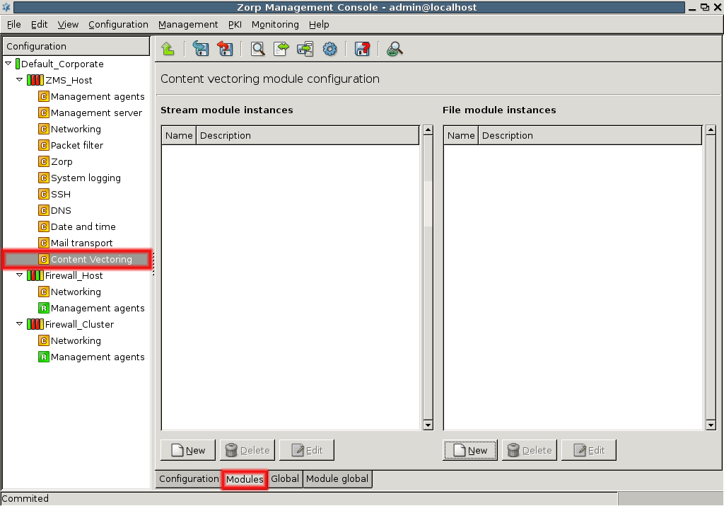
Module instances are the elements of the available CF modules configured for a particular content vectoring task. A data stream or an object can be inspected by one or more module instances. Module instances can be created and configured on the tab of the MC component. The panel has two distinct sections, the left one manages stream modules, the right one file modules. The functionality and handling of the two management interface is identical. Existing module instances are shown in the main section of the panel, organized into a tree based on the module they represent (nod32, html, and so on). Below this list are buttons to create, delete and edit module instances.
To create a new module instance, complete the following procedure:
14.2.1.1. Procedure – Creating a new module instance
-
Click on the button below the stream/file module instances list.
-
Select the module to be configured from the combobox.
Enter a name (and optionally a description) describing the instance.
-
Set the parameters of the module using the section of the dialog window. The available options are module specific and are described in Section 14.2.1.2, CF modules.
-
Some modules have global options that apply to all instances of the module. These options can be set on the tab. The global options available for the module are detailed in the description of the module.
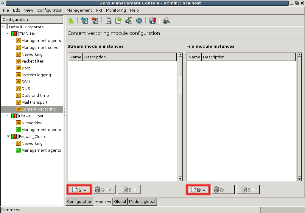
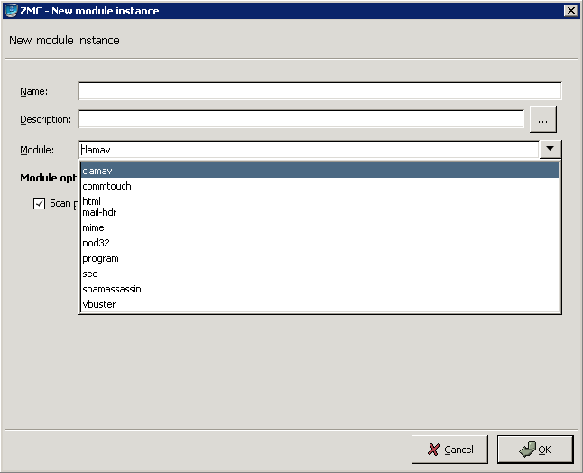
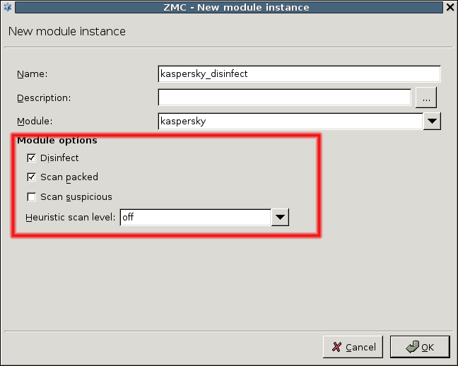
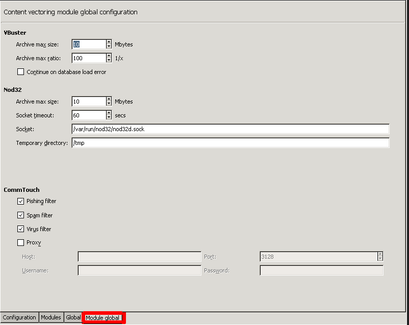
Each module available in CF has its own parameters that can be set separately for each module instance. Some of modules have global options that apply to all instances of that module, these are also described at the particular module.
The clamav module uses the Clam AntiVirus engine to examine incoming files. It supports only file mode and only detects infected files; it does not attempt to disinfect them. Starting with PNS 3.4, the module automatically scans archived files as well.
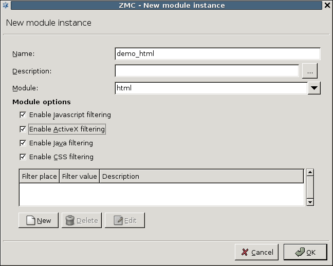
The HTML module can be used to filter various scripts and tags in HTML pages. It can operate both in file and stream mode. The HTML module has the following options:
: Remove all JavaScripts. Enabling this option removes all
javascriptandscripttags, and the conditional value prefixes (for example,onclick,onreset, and so on).: Remove all ActiveX components. Enabling this option removes the
applettags and theclassidvalue prefix.: Remove all Java code references. Enabling this option removes the
java:andapplication/java-archiveinclusions, as well as theapplettags.: Remove cascading stylesheet (CSS) elements. Enabling this option removes the single
linktags, thestyletags and options, as well as theclassoptions.-
: Custom filters can be added to remove certain elements of the HTML code using the button. The filter can remove the specified values from HTML tags, single tags, options and prefixes (specified through the combobox). The specifies the name of the tag/header to be removed.
The options of the parameter have the following meanings:
In tags: Remove everything between the specified tag and its closing tag. Embedded structures are also handled.
In single tags: Remove all occurrences of the specified single tag. A single tag is a tag that does not have a closing element, for example,
img,hr, and so on).In options: Remove options and their values (for example,
width, and so on).In prefixes: Remove all options starting with the string set as . For example,
onwill remove all options likeonclick, and so on.
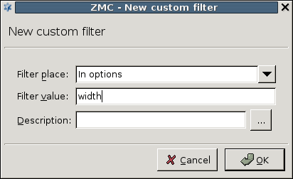
| Note |
|---|
The HTML module is designed to process only text data. It cannot handle binary data, thus directing binary files to the module should be avoided. |
The nod32 module uses the Nod32 virus filtering engine to examine incoming files. It supports only file mode. The module has the following parameters:
: Attempt to remove the virus from infected files.
: Perform virus scanning on archived files.
: Perform virus scanning on suspicious files (for example, suspicious files are often new variants of known viruses).
: Level of heuristic (non-database based) sensitivity. The available levels are
OFF, andNORMAL.
The nod32 module also has global options that apply to all instances of the module. These options can be set on the tab.
: Archived files larger than the specified value (in megabytes) are not scanned. For example, if a 2.5 MB .zip file contains a file that is 80 MB uncompressed, and the option is set to 10 MB, the file will not be scanned for viruses. However, if the option is set to 100 MB, CF will scan the file.
: Timeout value in secnds.
: The domain socket used to communicate with the nod32 engine. Default value: /var/run/nod32/nod32d.sock
: Path to the temporary directory used by the Nod32 engine.
The mail-hdr module can filter and maniputale e-mail headers in both stream and file mode. It scans the incoming e-mail (stream or file) using regular expressions and deletes or modifies the matching headers. New headers can also be inserted into the mails.
| Warning |
|---|
E-mail headers are processed and manipulated line-by-line. However, a header can span multiple lines. |
A single instance can include multiple filters; the order these filters are processed can be set using the arrow buttons. Each filter consists of a pattern, an action that is performed when the pattern is found, and an argument (for example, a replacement header). Note that not every action requires an argument.
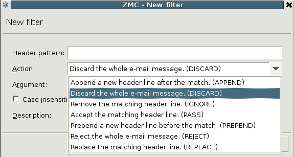
A filter has the following parameters:
: The search string to be found in the headers. Regular expressions can be used. The following options are also available for regular expressions:
-
: The action to be performed on the header line or the whole message if the pattern is found in the message. The following actions are available:
Append: Add the argument of the filter as a new header line after the match.
Discard: Discard the entire e-mail message. The argument is returned to the mail server sending the message as an error message.
Ignore: Remove the matching header line from the message.
Pass: Accept the matching header line. This action can be used to create exceptions from other filter rules.
Prepend: Add the argument of the filter as a new header line before the match.
Reject: Reject the entire e-mail message. The argument is returned to the sender of the message as an error message.
Replace: Replace the mathing header line to the argument of the filter.
: The will be replaced with this string if found in the stream. The replacement can contain \n (n being a number from 1 to 9, inclusive) references, which refer to the portion of the match which is contained between the nth \( and its matching \). Also, the replacement can contain unescaped & characters which will reference the whole matched portion of the pattern space.
: The case sensitive mode can be disabled by selecting this checkbox.
The mime module inspects and filters MIME objects (that is, mail attachments). It can check the MIME headers that describe the objects for validity, and also call a virus filtering CF module to scan the object for viruses. The mime module supports only file mode. The module has the following parameters:
: The maximal number of headers permitted in a MIME object. The object is removed if it exceeds this limit.
: The maximal length of a header in characters. Applies to the total length of the header. The header is removed if it exceeds this limit.
: The maximal length of a header line in characters. Applies to every single line of the header. The header is removed if it exceeds this limit.
-
: If enabled, headers not complying to the related RFCs or violating the limits set in the previous options are automatically removed (dropped).
Warning If is disabled and an invalid header is found, the entire object (for example, e-mail) is rejected.
: By default, the
mimeCF module replaces the removed objects (attachments) with the following note that informs the recipient of the message about the removed attachments: The original content of this attachment was rejected by local policy settings. If the option is enabled, no note is added to the e-mail.: If disabled, the
mimemodule does not modify the messages.: The
mimeCF module can automatically add a MIME object to the inspected messages. To use this feature, verify that the option is enabled, select , paste the MIME object into the appearing dialog box, and select .
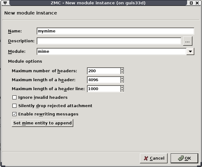
To scan the actual MIME objects (for example, the attachments of an e-mail) for viruses, you have to create a special rule group called mime-data. Use this as the name of the rule group, and add a virus filtering module (for example, clamav) to this rule group. When the mime module is scanning an e-mail message, it will inspect the attachments, then pass the attachment to the mime-data rule group to scan for viruses. See Section 14.2.3, Routers and rule groups for details on creating rule groups.
The program module is general wrapper for third-party applications capable to work in stream or file mode. The stream or file is passed to the application set in the field.
A single instance can include multiple filters; the order these filters are processed can be set using the arrow buttons.
A program module has the following parameters:
: The application to be executed.
: If the application set in the field does not provide a return value within this interval, it is assumed to be frozen.
: The program may make changes to the data and return the modified version to CF.
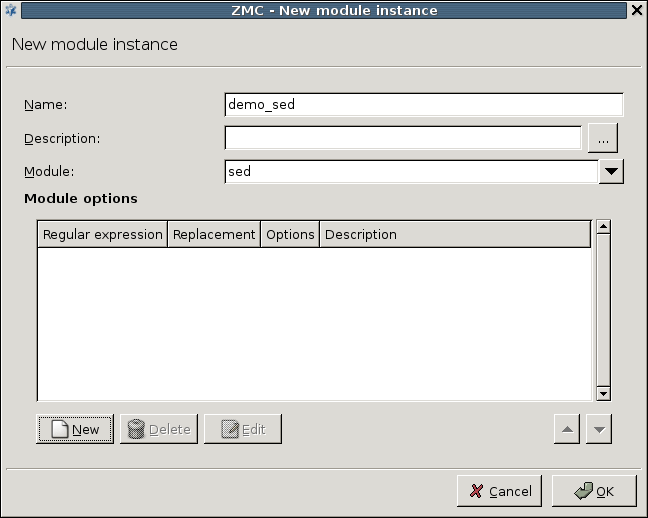
The sed module is a stream editor capable to work in both stream and file mode. It scans the target stream and replaces the string to be found (specified as a regular expression) with another string.
| Warning |
|---|
This module is similar to, but not identical with the common UNIX sed command. |
A single instance can include multiple filters; the order these filters are processed can be set using the arrow buttons.
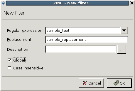
A filter has the following parameters:
: The search string to be found in the stream. Regular expressions can be used. The following options are also available for regular expressions:
: The will be replaced with this string if found in the stream. The replacement can contain \n (n being a number from 1 to 9, inclusive) references, which refer to the portion of the match which is contained between the nth \( and its matching \). Also, the replacement can contain unescaped & characters which will reference the whole matched portion of the pattern space.
: Replace all occurrences of the search string. If not checked, the filter will replace only the first occurrence of the string.
: Disable case sensitive mode.
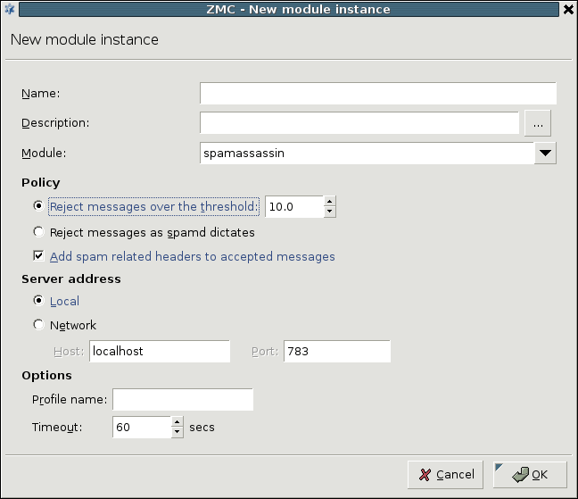
The spamassassin module uses the Spamassassin spam filtering engine to examine incoming e-mails. It supports only file mode. The module has the following parameters:
-
Policy related options
Reject messages over the threshold: Reject the message only if its spam status By default, SpamAssassin rejects all e-mails with a spam status (called
required_scorein SpamAssassin terminology) higher than 5 as spam. However, to minimize the impact of false positive alarms, if the spam status of an email (as calculated by SpamAssassin) is over therequired_score, but below the value set in threshold, CF only marks the e-mail as spam, but does reject it. If the spam status of an e-mail is above the threshold, it is automatically rejected.Reject messages as spamd dictates: Reject all e-mails detected as spam by SpamAssassin.
-
Add spam related headers to accepted messages: Append headers to the e-mail containig information about SpamAssassin, the spam status of the e-mail, and so on. Sample headers are presented below.
X-Spam-Checker-Version: SpamAssassin 3.0.3 (2005-04-27) on mailserver.example.com X-Spam-Level: X-Spam-Status: No, score=-1.7 required=5.0 tests=BAYES_00 autolearn=ham version=3.0.3
-
Server address
Local: SpamAssassin is running on the same host as CF. In this case, communication is performed through a UNIX domain socket.
Network: SpamAssassin is running on a remote machine. Specify its address and the port SpamAssassin is accepting connections in the and fields, respectively.
-
Other options
Profile name: The user under which SpamAssassin should filter e-mails. Default value: not set, the user running SpamAssassin is used (usually
nobody).Timeout: Timeout value for SpamAssassin.
Scanpaths are lists of module instances and some settings (trickling mode, quarantining, and so on) specific to the given scanpath. Traffic directed to a scanpath is inspected by the module instances specified in the scanpath. Scanpaths can include both stream and file modules, but always the stream modules process the data first.
Scanpaths can be managed (created, deleted and edited) from the section of the tab of the MC component. To configure a new scanpath, the following procedure must be completed:
14.2.2.1. Procedure – Creating a new scanpath
-
Click on in the section of the tab of the MC component.
Enter a name (and optionally a description) for the scanpath.
-
Use the buttons and select the stream and/or file module instances to be added to the scanpath. It is not necessary to use existing module instances, they can be also created on-the-fly using the button of the dialog window.
The data is processed in the order the module instances are listed (starting always with the stream modules). The order of instances can be changed using the arrow buttons below the lists.
Set and configure the quarantine and trickling mode to be used for the scanpath. Also set the policy for large files. These options are described in Section 14.2.2.2, Scanpath options.
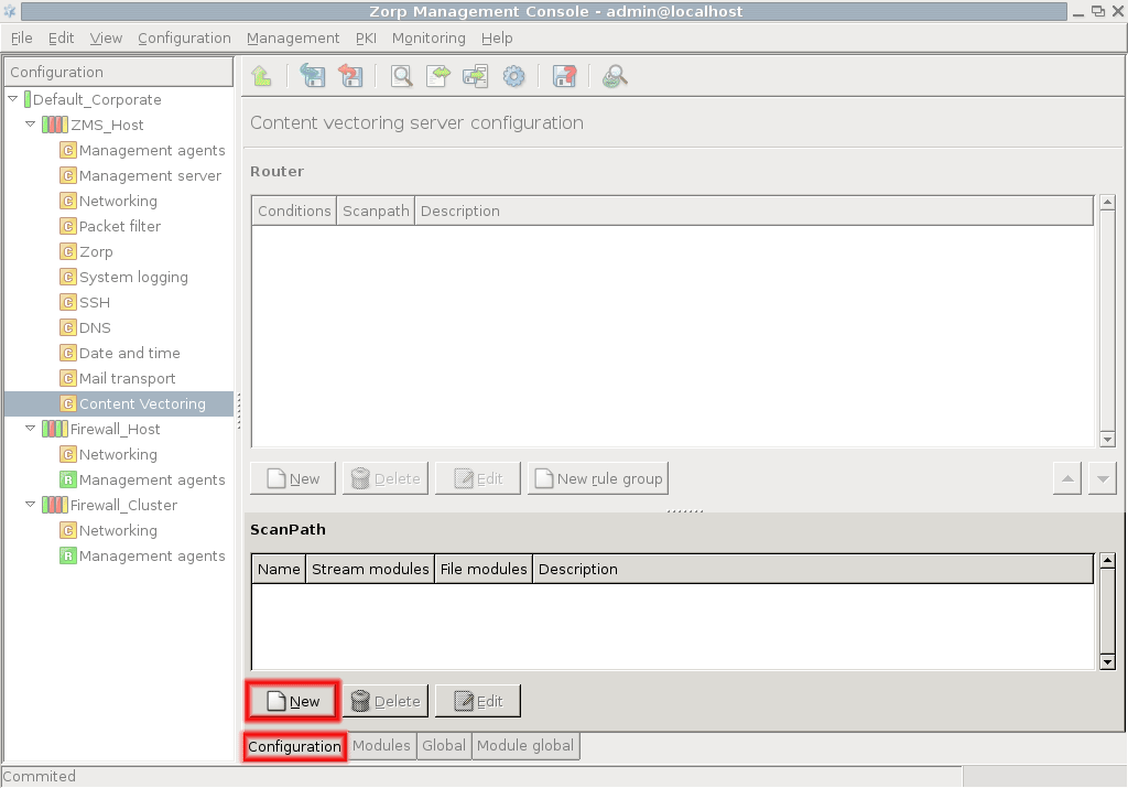
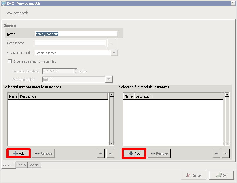
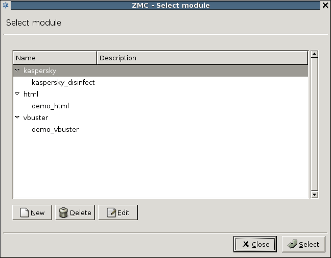
The following sections describe the options available for scanpaths. The options can be configured on the , , tabs of the scanpath dialog.
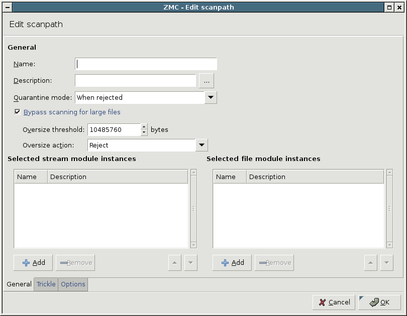
specifies when to store an infected in the quarantine. Always the original file is stored.
: Quarantine all objects rejected for any reason.
: Quarantine objects that could not be disinfected.
: Quarantine only the original version of the files which were successfully disinfected. For example, if an infected object is found but it is successfully disinfected, the original (infected) object is quarantined. That way, the object is retained even if the disinfection damages some important information.
: Disable quarantining; objects rejected for any reason are dropped.
: By default, all files arriving to the scanpath are scanned. However, because of performance resons this might not be optimal, particularly if large files (for example, ISO images) are often downloaded through the firewall. Therefore it is possible to specify an value and an . If the checkbox is selected, then objects larger than (in bytes) are not scanned, but accepted or rejected, as set in . It is also possible to return an error message for oversized files.
Content filtering cannot be performed on partial files — the entire file has to be available on the firewall. Sending of the file to the client is started only if no virus was found (or the file was successfully disinfected). Instead of receiving the data in a continuous stream, as when connecting to the server “regularly”, the client does not receive any data for a while, then “suddenly” it starts to flow. This phenomena is not a problem for small files, since these are transmitted and checked fast, probably without the user ever noticing the delay, but can be an issue for larger files when the client application might time out. Another source of annoyance can be when the bandwidth of the network on the client and server side of the firewall is significantly different. In order to avoid time outs, a solution called trickling is used. This means that the firewall starts to send small pieces of data to the client so it feels that it is receiving something and does not time out. For further information on trickling, see the Virus filtering and HTTP Technical White Paper available at the Documentation Page at https://docs.balasys.hu/. CF supports the following trickling modes. These can be set on the tab of the scanpath editor dialog.
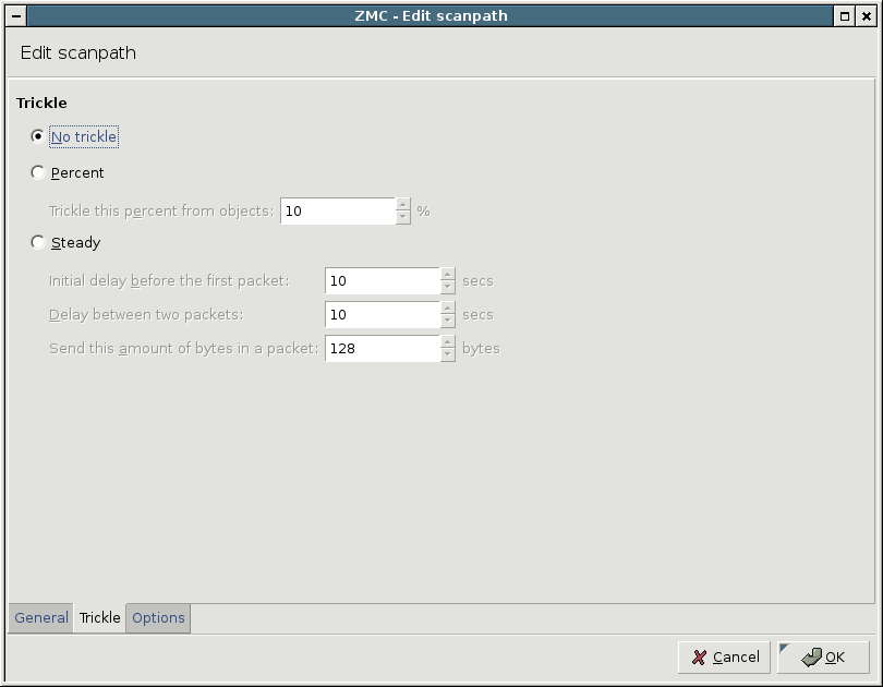
: Trickling is completely disabled. This may result in many connection timeouts if the processing is slow, or large files are downloaded on a slow network.
: Determine the amount of data to be trickled based on the size of the object. Data is sent to the client only when CF receives new data; the size of the data trickled is the set percentage of the total data received so far.
: Trickle fixed amount of data in fixed time intervals. Trickling is started only after the period set in . If the whole file is downloaded and processed within this interval, no trickling is used.
| Tip |
|---|
It is recommended to use the percent-based trickling method, because the chance of an operable virus trickling through the system unnoticed is higher when steady trickling is used. |
CF can automatically decompress gzipped files and transmission and pass the uncompressed data to the modules. After the modules process the data, CF can recompress it and return it to PNS. To enable the automatic decompressing, select the checkbox. The compression level of the recompressed data can be set using the spinbutton.
| Note |
|---|
Compression level of 5 or higher can significantly increase the load on the CPU. |
The following actions can be set for the gzip headers through the combobox:
Leave all gzip headers intact: Do not modify the headers.
Leave filename headers intact: Retain the headers containing filenames, remove all other ones.
Remove all gzip headers: Strip all headers.
In some cases it is possible that a module or CF cannot check an object for some reason (for example the file is corrupted, or the license of the module has expired). In such situations CF rejects all objects by default. Exemptions can be set for the errors described below: check the errors for which all objects should be accepted.
Corrupted file: The file is corrupt and cannot be decompressed. Certain virus scanning module handle encrypted or password-protected files as corrupted files.
Encrypted file: The file is encrypted or password-protected and cannot be decompressed.
Unsupported archive: The file is compressed with an unknown/unsupported compression method and cannot be decompressed.
Engine warning: The file is suspicious, heuristic virus scanning detected the file as possibly infected.
OS error: A low level error occurred (the module ran out of memory, or could not access the file for some reason).
Engine error: An internal error occurred in the module while scanning the file.
License error: The license of the module has expired.
Routers are simple conditional rules (that is, if-then expressions) that determine how the received object has to be inspected. They consist of a condition and a corresponding action: if the parameter of the traffic (or file) matches the set condition, then the action is performed. The condition consists of a variable and a pattern: the condition is true if the variable of the inspected object is equal to the specified pattern. The action can be a default action (for example, ACCEPT, REJECT, and so on) or a scanpath. Routers cannot be used on their own, they must belong to a rule group. A rule group is a list of routers, defining a set of conditions that are evaluated one-by-one for a given scenario. Rule groups also have a default action or scanpath that is performed if none of the set conditions match the received object. Rule groups are also important because a PNS proxy can send data only to a rule group, and not to a specific router (see Section 14.2.4, Configuring PNS proxies to use CF for details).
| Warning |
|---|
Only the action or scanpath corresponding to the first matching condition is performed, therefore the order of the routers in a rule group is very important. |
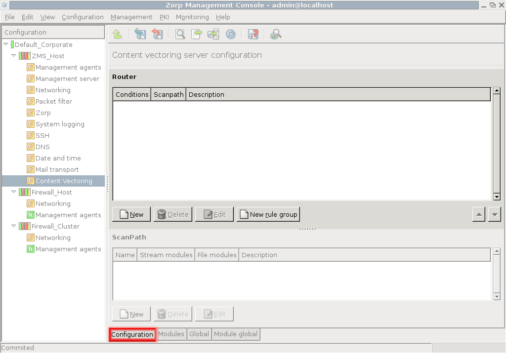
Routers and rule groups can be managed (created, deleted and edited) from the section of the tab of the MC component. The defined rule groups and their corresponding routers (conditions and actions) are displayed as a sortable tree.
| Tip |
|---|
Rule groups and routers can be disabled from the local menu if they are temporarily not needed. |
To create and configure a set of routers, complete the following procedure:
14.2.3.1. Procedure – Creating and configuring routers
Navigate to the tab of the MC component.
-
Click on . Enter a name for the rule group (scenario) and select a default action or specify a scanpath to be used as default.
-
Select the newly created rule group, and click on to add a new router to the group.
Select the action to be performed if the conditions match using the combobox. The available actions are described in Section 14.2.3.2, Router actions and conditions.
-
Click on , and define a condition for the router. Select the variable to be used from the combobox, and enter the search term to the field. Wildcards (for example, '*', '?') can be used in the pattern. If the of the inspected object matches , the action specified in will be performed.
Note A router can contain multiple conditions. In this case the target action is performed only if all specified conditions are true.
-
Add as many routers to the rule group as required.
Warning The routers are evaluated sequentially (much like packet filtering rules), therefore it is important to list them in a correct order. The order of the routers in a rule group can be modified using the arrow buttons below the routers tree. The object is only inspected with the scanpath of the first matching router.
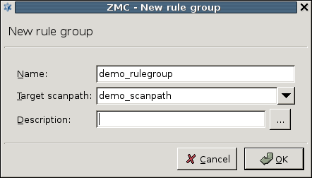
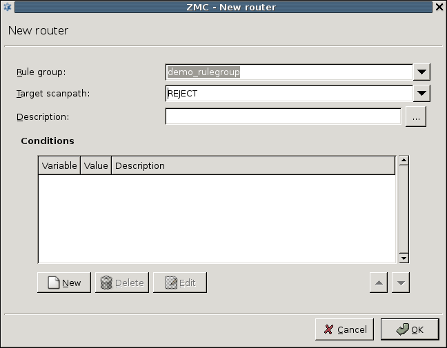
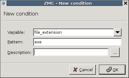
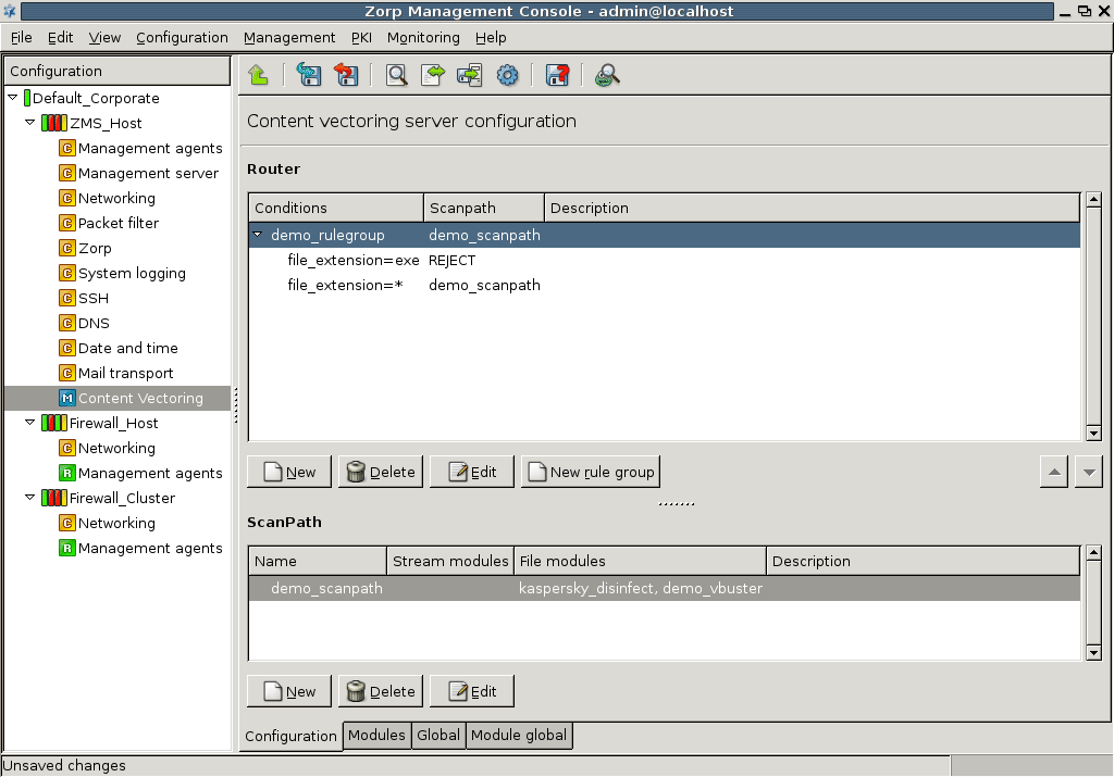
The following actions are available:
: Accept (allow it to pass the firewall) the object.
: Accept the object, but also store a copy of it in the quarantine.
: Drop the object.
: Drop the object, but store a copy of it in the quarantine. That way, it can be retrieved later if needed.
: Inspect the object according to the specified scanpath.
The following table describes some of the variables that can be used in the conditions. This table does not list all such variables, as new variables are added periodically. For an up-to-date list of the available variables see zcv.cfg(5) in Proxedo Network Security Suite 1.0 Reference Guide, or issue the man zcv.cfg command from a shell on the CF host.
zorp_protocol: Protocol used to transfer the object.
file_name: File name or URL. of the object.
content_type: MIME type of the object as specified by the peer.
zorp_server_address.ip: IP address of the server.
| Tip |
|---|
The combobox used to create new conditions lists all available variables. |
CF can only inspect files or streams it receives from PNS proxies. PNS proxies send data to CF as they would stack another proxy.
The following procedure describes how to configure the communication between PNS proxies and CF.
14.2.4.1. Procedure – Configuring communication between PNS proxies and CF
-
First, the connection settings of CF have to be configured in the section on the tab of the MC component. Specify either the IP address/port pair on which CF should accept connections, or the radiobutton if CF will communicate with PNS through UNIX domain sockets.
Note The same bind settings will have to be used when the Stacking provider is configured in the tab of the MC component (see Section 6.7.7, Stacking providers for details). These settings are required because PNS and CF do not necessarily run on the same hosts.
-
Navigate to the tab of the MC component and create a new Stacking Provider. Specify the same connection settings to this stacking provider as set to CF in the previous step.
Note A Stacking provider can contain the connection parameters (that is, IP/port pair) of multiple CF hosts. If more than one hosts are specified, PNS will automatically balance the load sent to these hosts using the round-robin algorithm.
-
Navigate to the tab of the MC component, and select the proxy class that will send the data to CF for inspection. This can be an existing or a newly derived proxy class (for example,
MyFtpProxy). Add the desired stack attribute of the proxy to the (for example,
self.request_stack). For details on the stack attributes of the different proxy classes see the description of the proxy class in Chapter 4, Proxies in Proxedo Network Security Suite 1.0 Reference Guide.-
Select the stack attribute and click on . Click on , and add a key identifying the element of the particular protocol that should be sent over to CF for inspection (for example,
*). For details, see the description of the proxy class in Chapter 4, Proxies in Proxedo Network Security Suite 1.0 Reference Guide. Enable stacking by setting the attribute to
type_ftp_stk_dataof the key using the combobox of the column, then click .-
Click on , select the
zorp_stackattribute in the appearing window, and click again on . -
Set to Stacking provider. Select the stacking provider configured in Step 2 from the combobox, and the rule group to be used from the combobox.
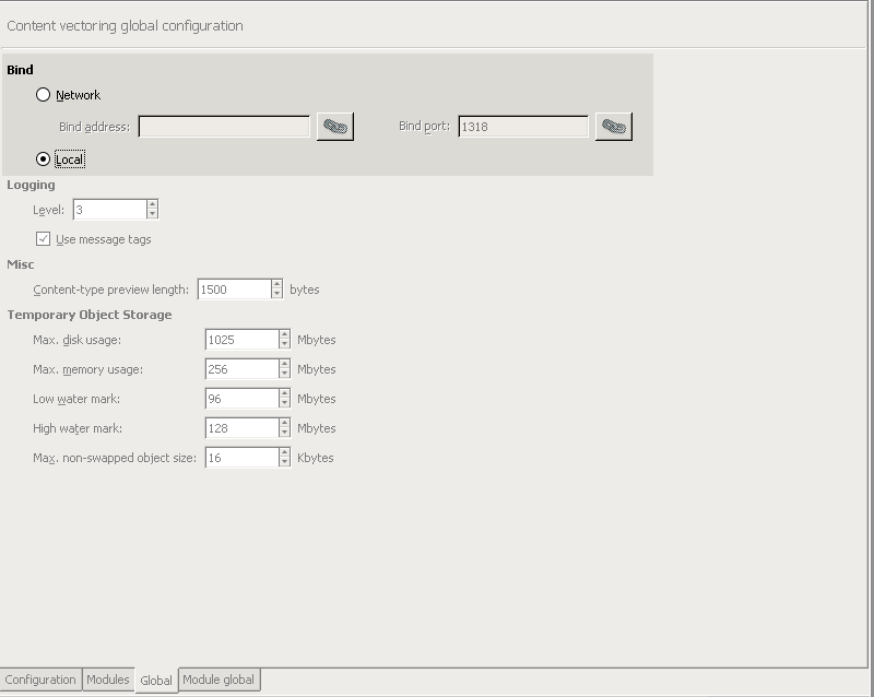
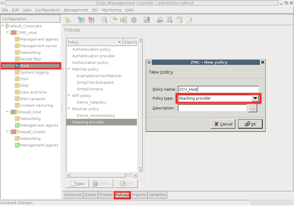
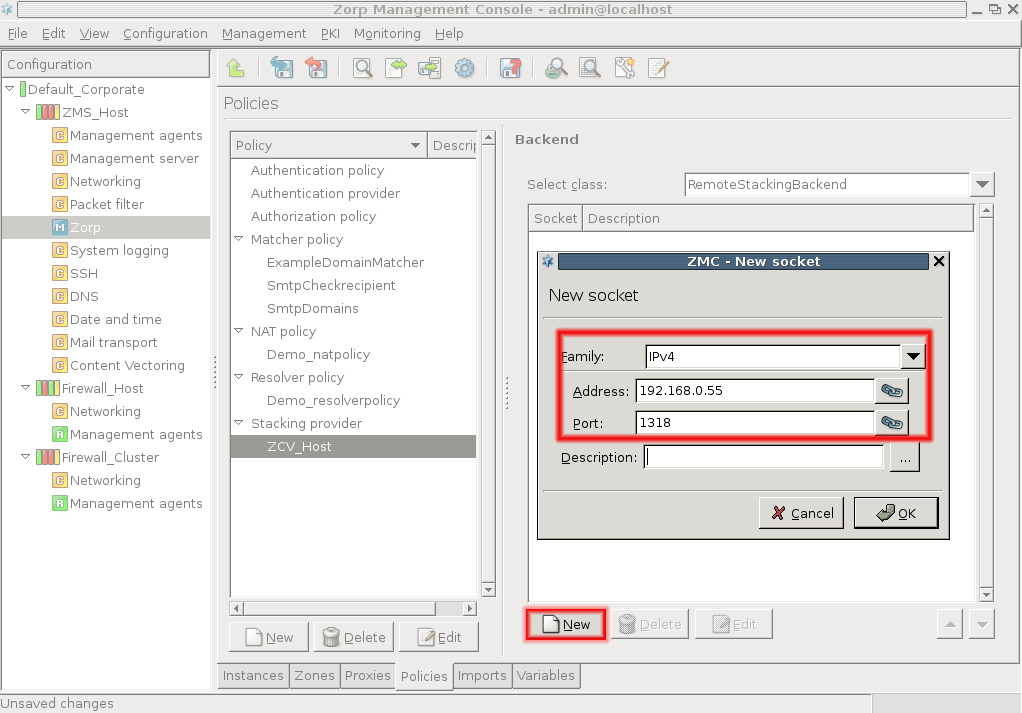
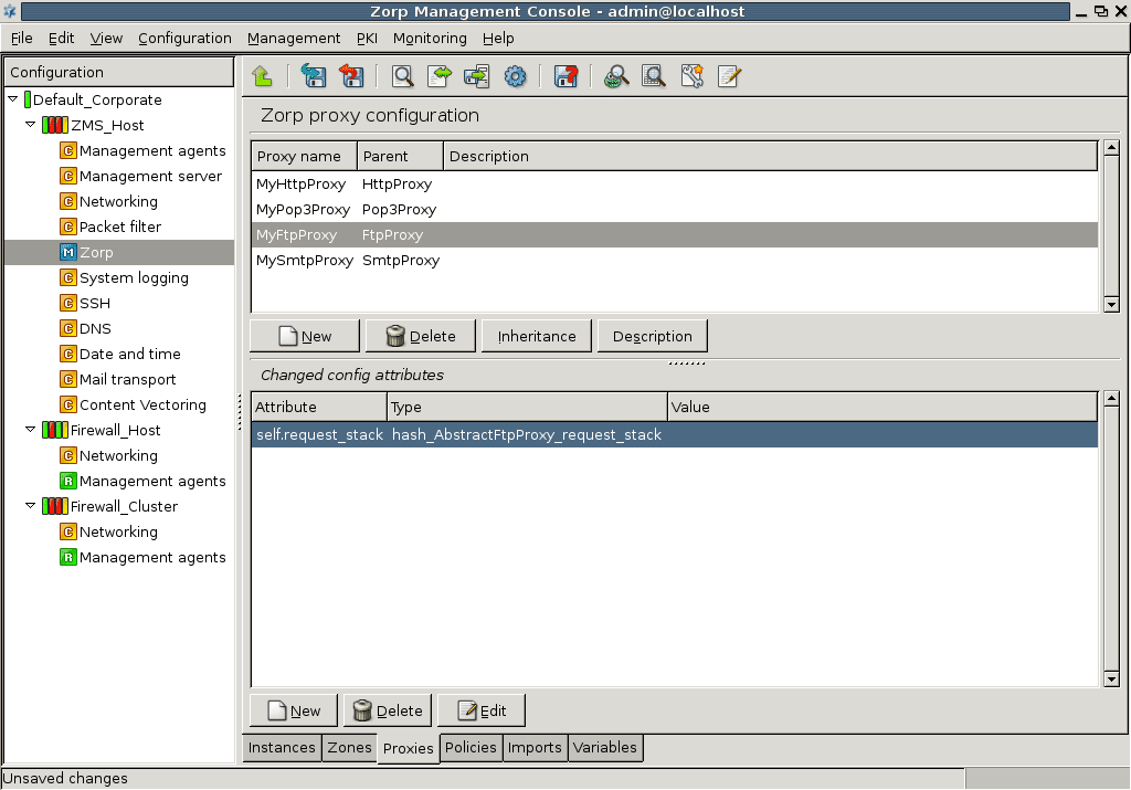
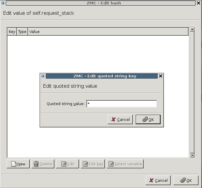
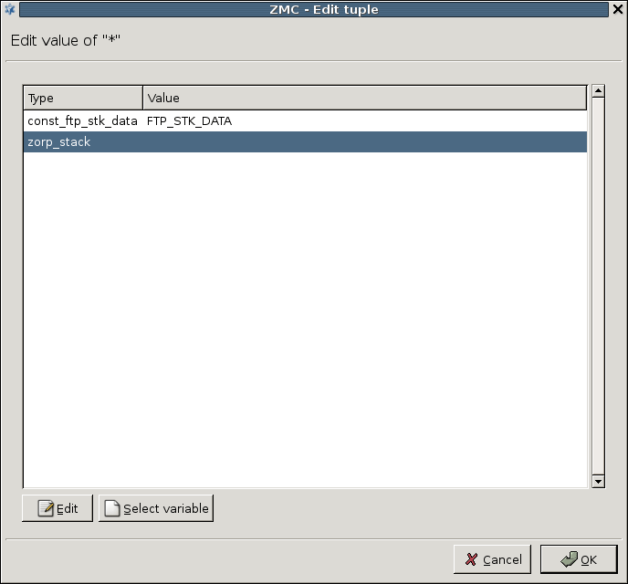
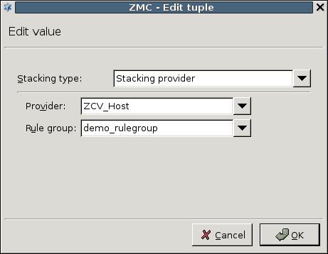
A number of global settings affecting the performance and resource use of CF can be configured on the tab of the MC component. These are discussed in the following sections.
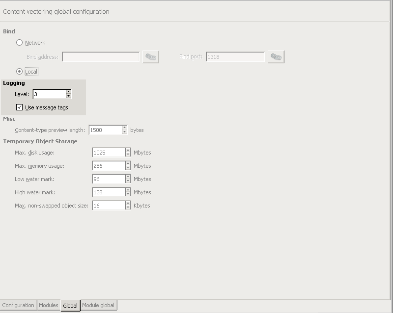
The parameters related to logging in CF are the following:
: Verbosity level of the logs. Level 3 is the default value, and is usually sufficient. Level 0 produces no logs messages, while 10 logs every small event, and should only be used for debugging purposes.
: Enable the logging of message tags.
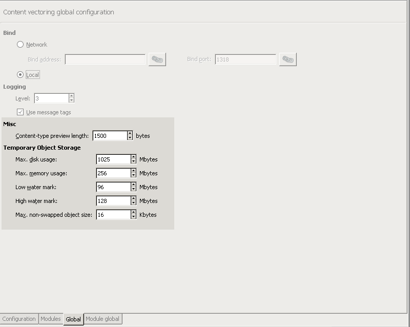
CF has a number of options governing the memory and hard disk usage behavior of CF. These resources are mainly used to temporarily store the objects while being inspected, decompress archived files, and so on. The following memory usage settings are available:
: The maximum amount of hard disk space that CF is allowed to use.
: The maximum amount of memory that CF is allowed to use.
: CF tries to store everything in the memory if possible. If the memory usage of CF reaches
high water mark, it starts to swap the data onto the hard disk, until the memory usage decreases tolow water mark.: Objects smaller than this value are never swapped to hard disk.
: This parameter determines the amount of data (in bytes) read from MIME objects to detect their MIME-type. Higher value increases the precision of MIME-type detection. Trying to detect the MIME-type of objects is required because there is no guarantee that a MIME object is indeed what it claims to be.
All CF modules use a common quarantine on each host. The contents of the quarantine on a particular host can be accessed through the  icon that is available on the , , and components. The main part of this window shows a list of the quarantined files, including columns of meta-information like their date, size, why they were quarantined, and so on. For a detailed list of the possible meta-information see Section 14.3.1, Information stored about quarantined objects. The objects in the quarantine can be sorted by clicking on any of these columns. The order of the columns can be simply modified by dragging the column header to its desired place.
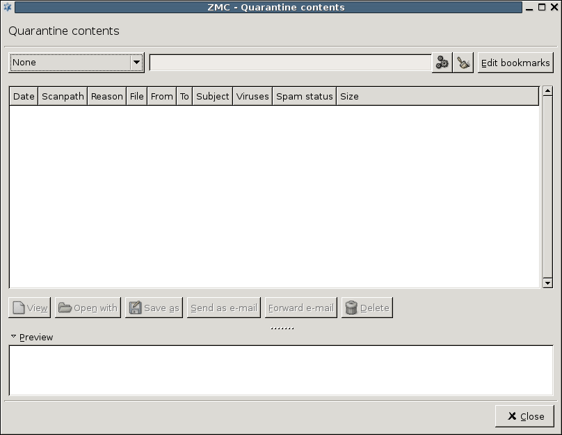
The window is a Filter window, thus various simple and advanced filtering expressions can be used to display only the required information. For details on the use and capabilities of Filter windows, see Section 3.3.10, Filtering list entries.
The lower section of the window contains a command bar to manipulate the selected objects, and a preview box displaying the first 4 Kb of the file. The following options are available from the command bar:
-
: Display the entire file in a new window.
: Open the object with the specified application. The application will be started on the local machine running MC.
: Save the object to the local machine running MC.
: Send the selected object(s) as e-mail attachment to the destination address specified in the appearing dialog window.
: Forward the selected e-mail to the destination address specified in the appearing dialog window. This option is available only to quarantined e-mails.
: Delete the selected object(s).
| Tip |
|---|
and can be used at once on multiple selected objects. |
In case of clusters, the command bar includes a node-selection combobox, that allows to display the contents of all nodes, or only a specified one.
The following meta-information is stored about the objects in the quarantine:
: IP address and port of the client receiving the quarantined object.
: The zone that the client belongs to.
: Date when the object was quarantined.
: Detailed description of the verdict.
: The direction the quarantined object was transferred (that is,
uploadordownload).: MIME-type of the quarantined object as detected by CF.
: File name or URL of the quarantined object.
: A unique identifier of the file in the quarantine.
: The sender address (in case of e-mails).
: The user who tried to access the object belongs to the listed usergroups.
: Kind of the quarantined content:
file,e-mail, ornewsnet post.: The HTTP method (for example,
GET,POST) in which the quarantined object was detected.: The program that quarantined the object (usually CF or PNS).
: The protocol in which the quarantined object was found.
: Name of the proxy class that requested content vectoring on the quarantined object.
: The envelope recipient addresses of the object (only in SMTP).
: The reason why the object was quarantined (for example, detected as virus, spam, and so on).
: The CF rule group that was stacked by the proxy.
: The scanpath that quarantined the object.
: The envelope sender address of the object (only in SMTP).
: IP address and port of the server sending the quarantined object.
: The zone that the server belongs to.
: ID of the session which requested content vectoring on the quarantined object.
: Size of the object in bytes.
: Indicates if the e-mail is detected as spam.
: The subject of the e-mail.
: The recipient address (in case of e-mails).
: MIME-type of the quarantined object according to its MIME header.
: Name of the user who tried to access (for example, download) the object.
: The decision that caused the object to be quarantined (for example,
REJECT,ACCEPT_QUARANTINE, and so on): The virus(es) detected in the object.
Naturally, only the information relevant to the specific object is available, for example, an infected file downloaded through HTTP does not have subject, and so on.
Quarantine cleanup on a host can be configured from the tab of the given component in MC. This interface can be used to create rules that determine when are objects deleted from the quarantine.
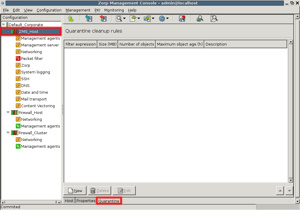
The main section of the tab displays the currently effective rules (including disabled ones), and the control buttons for managing (creating, deleting, and editing) them. A rule consists of a filter that determines the scope (the effected objects) of the rule, and limitations on the storage of such objects. The available filtering expressions are the same as used in the filter optons of the panel (see Section 14.3, Quarantine management in MC). The following options can be used to set limitations on the stored objects:
: Maximum hard disk space used to store the objects. Objects exceeding this limit are deleted (starting with the oldest object).
: Maximum number of stored objects. Objects exceeding this limit are deleted (starting with the oldest object).
: Objects older than the specified value are deleted (starting with the oldest object).
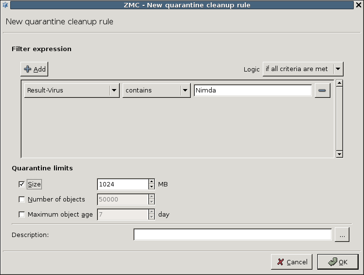
The limitations only apply to the objects matching the set filter expression. For example, setting the filter expression to Result-Virus matches X and the limit to 256 MBytes means that a maximum of 256 MBytes of objects will be stored in the quarantine that are infected with the X virus.
| Tip |
|---|
The limitations are global if no filter is specified. |
Rules are evaluated and executed sequentially; if contradicting rules are found, the strictest one will be effective.
User authentication verifies the identity of the user trying to access a particular network service. When performed on the connection level, that enables the full auditing of the network traffic. Authentication is often used in conjunction with authorization — allowing access to a service only to clients who have the right to do so.
Authentication is a method to ensure that certain services (access to a server, and so on) can be used only by the clients allowed to access the service. The process generally called as authentication actually consists of three distinct steps:
Identification: Determining the clients identity (for example, requesting a username).
Authentication: Verifying the clients identity (for example, requesting a password that only the real client knows).
-
Authorization: Granting access to the service (for example, verifying that the authenticated client is allowed to access the service).
Note It is important to note that although authentication and authorization are usually used together, they can also be used independently. Authentication verifies the identity of the client. There are situations where authentication is sufficient, because all users are allowed to access the services, only the event and the user's identity has to be logged. On the other hand, authorization is also possible without authentication, for example if access to a service is time-limited (for example, it can only be accessed outside the normal work-hours, and so on). In such situations authentication is not needed.
Verifying the clients identity requires an authentication method based on something the client knows (for example, password, the response to a challenge, and so on), or what the client has (for example, a token, a certificate, and so on). Traditionally, firewalls authenticate the incoming connections based on the source IP of the connection: if a user has access (can log in) to that computer, he has the right to use the services. However, there are several problems with this approach. IP addresses can be easily forged (especially on the local network), and are not necessarily static (for example, when DHCP is used). Furthermore, this method cannot distinguish the different users who are using a single computer (for example, in a terminal server or hot-desking environment). For these reasons, authentication is most commonly left to the server application providing the particular service. However, PNS is capable to overcome these problems in a simple, user-friendly way.
Most protocols (for example, HTTP, FTP) capable of authentication offer only inband authentication, meaning that the client must authenticate himself on the server. The advantage of inband authentication is that it is an internal part of the protocol, and most client applications support it. The disadvantage is that many protocols do not support any form of authentication, and those that do support only a few authentication methods. Usually in an organization it is desirable to use only a single (strong) authentication method, however, not all protocols are suitable for all methods.
| Note |
|---|
A few protocols support authentication on the firewall as well, in this case the client actually has to authenticate himself twice: once on the firewall, once on the server. |
Outband authentication is performed independently of the service and the protocol in a separate communication channel. Consequently, any protocol can be authenticated, and the authentication method does not depend on the protocol. That way every protocol can be authenticated with a single authentication method. The only disadvantage of outband authentication is that a special client application (for example, the ;Authentication Agent) has to be installed and configured on all client machines.
The process of outband authentication using the authentication agent is illustrated on the figure below.
15.1.2.1. Procedure – Outband authentication using the Authentication Agent
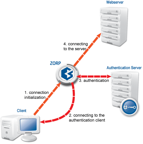
The client tries to connect to the server.
PNS connects to the authentication agent of the client.
-
The actual authentication is performed:
Username
Authentication method selection.
Authentication according to the selected method.
If the authentication is successful, the connection to the server is established.
AS is a tool that allows PNS services to be authenticated against existing user databases (backends). AS does not itself provide authentication services, it only mediates between PNS and the backends. The traditional access control model in PNS is based on verifying that a connection requesting a service from a source zone is allowed to access the service, and that the service is allowed to enter the destination zone. That is:
The client must belong to a zone where the particular service can be initiated (outbound service).
The service must be allowed to enter (inbound service) the destination zone.
Using AS to authenticate the connections adds further requirements to this model: the client must successfully authenticate himself, and (optionally) must be allowed to access the service (that is, authorization can be also required). The actual procedure is as follows:
When the client initiates a connection, it actually tries to use a PNS service. PNS checks if an authentication policy is associated to the service. If an authentication policy is present, PNS contacts a AS server (the authentication provider specified in the authentication policy). The AS server can connect to a user database (a backend) storing user information (passwords, certificates, and so on) required for a particular authentication method. (The type of the database determines which authentication methods can be used.) Each instance of a AS server can connect to a single backend, but multiple instances can be run from AS. When an authentication request arrives from PNS, AS evaluates a number of configured routers: rules that determine which instance should be used to authenticate the connection. This decision is based on meta-information of the connection received from PNS (for example, Client-IP, Username, and so on). The selected instance connects the client and the authentication is performed. The authentication can take place within the protocol (inband), or using a dedicated authentication agent (outband).
If the authentication is successful, PNS verifies that the client is allowed to access the service (by evaluating the authorization policy). If the client is authorized to access the service, the server-side connection is built. The client is automatically authorized if no authorization policy is assigned to the service.
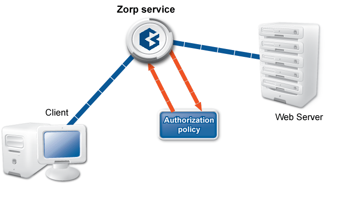
AS currently supports the following database backends:
: zas_db authenticates users against an LDAP database, supporting the following authentication methods:
username/password,S/Key,CryptoCard RB1,LDAP binding,GSSAPI/Kerberos5, andx.509.: Authentication through the traditional
htpasswdfile. Supports theusername/passwordauthentication method.: Authentication using Pluggable Authentication Modules. Any authentication method supported in PAM can be used.
: Authentication using a RADIUS server. Supports the
username/passwordandchallange/responseauthentication methods.
This section describes how to initialize and configure AS, and how to create the required PNS policies.
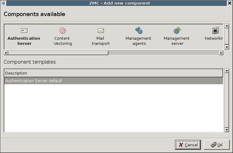
The various parameters of AS can be configured on the MC component. Before starting to configure AS, add this component to the host (see Procedure 3.2.1.3.1, Adding new configuration components to host for details).
AS instances using specific database backends can be configured in the section of the MC component. The existing instances and the type of database they use are displayed in a list; instances can be created, deleted, and modified using the control buttons below the list.
| Note |
|---|
Only unused instances can be deleted; if an instance is used in a router, the router has to be modified or deleted first. |
To create a new instance, complete the following procedure:
15.3.1.1.1. Procedure – Creating a new instance
-
Navigate to the MC component, and click on in the section.
-
Enter a name for the instance and select the type of the database this instance will connect to from the combobox. Options specific to the selected backend type will be displayed.
Configure the options of the backend. The available backends and their options are described in the following chapters. The permitted authentication methods can be also selected here.
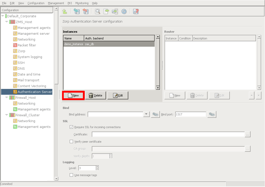
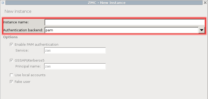
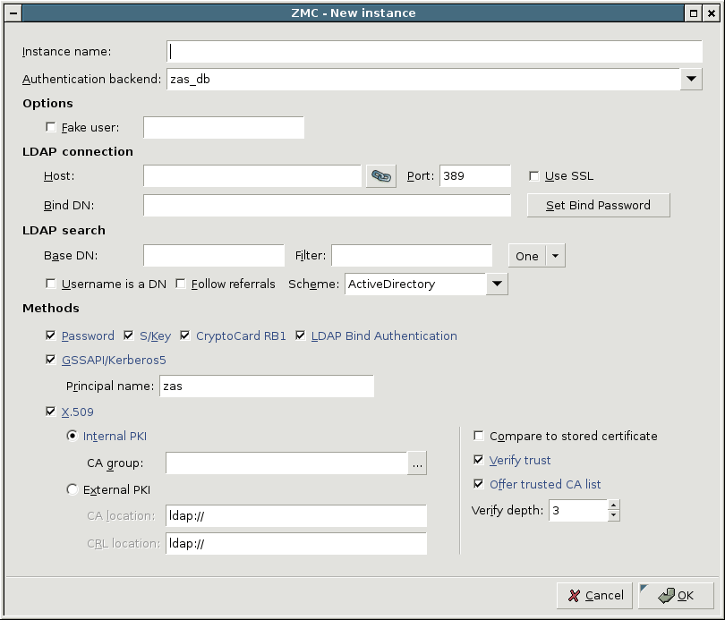
The zas_db backend authenticates users against an LDAP database using the Microsoft Active Directory, the POSIX, or the Novell eDirectory/NDS scheme. The backend has the following settings:
-
: Enable authentication faking. This requires a valid user account in the LDAP database that is exclusively used for this purpose. The user name of this account has to be set in the corresponding textbox.
Note All backends are capable of authentication faking. This is a method to hide the valid usernames, so that they cannot be guessed (for example using brute-force methods). If somebody tries to authenticate with a non-existing username, the attempt is not immediately rejected: the full authentication process is simulated (for example, password is requested, and so on), and rejected only at the end of the process. That way it is not possible to determine if the username itself was valid or not. It is highly recommended to enable this option.
-
: IP address of the LDAP server.
: Port number of the LDAP server.
: Enable SSL encryption to secure the communication between AS and the backend.
: Bind to this DN before accessing the database.
: The password to use when binding to LDAP.
-
:
: Perform queries using this DN as base.
: Search for accounts using this filter expression.
: Specifies the scope of the search.
base,sub, andoneare acceptable values, specifyingLDAP_SCOPE_BASE,LDAP_SCOPE_SUB, andLDAP_SCOPE_ONE, respectively.: Indicate that the incoming username is a fully qualified DN.
: If this option is set, AS will respect the referral response from the LDAP server when looking up a user.
-
: Specify LDAP scheme to use:
Active Directory,POSIX, orNDSstyle directory layout.Note Make sure to set
SchemetoActive Directorywhen using a Microsoft Active Directory server as a database backend.
-
: Select and configure the allowed authentication methods.
: Implements password authentication. Allow password authentication only if the connection between PNS and AS is secured (see Section 15.3.2, Authentication of PNS services with AS for details).
: S/Key based authentication.
: CryptoCard RB1 hardware token based authentication.
: Authentication against the target LDAP server. Only password authentication is supported by this method, therefore it is only available if the connection between AS and PNS is secured with SSL.
: GSSAPI based authentication. The representing this authentication service also has to be set.
-
: Authentication based on x.509 certificates. To use this method, a number of further options have to be specified:
The CA issuing the client certificates. This can be an internal CA group (managed by the PNS PKI, see Chapter 11, Key and certificate management in PNS for details), or an external one. In the latter case the locations of the trusted CA certificates and the corresponding CRLs have to be set as space-separated lists of
file://orldap://URLs.: Compare the stored certificate bit-by-bit to the certificate supplied by the client. The authentication will fail when the certificates do not match, even if the new certificate is trusted by the CA.
: Verify the validity of the certificate (that is, the certificate has to be issued by one of the trusted CAs and must not be revoked). This verification is independent from the , so if both parameters are set, both conditions must be fulfilled to accept the certificate.
: The maximum length of the verification chain.
: Send a list of trusted certificates to the client to choose from to narrow the list of available certificates.
-
: By default, AS accepts connections only from Authentication Agents (AA). Disable this option if you are using a different client to authenticate on AS, for example, if a web-browser authenticates using a client-side certificate.
Disabling this option works only with proxies that support inband authentication, for example, HTTP.
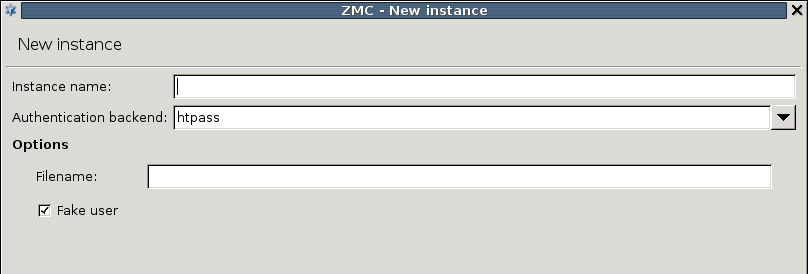
The backend authenticates users against an Apache htpasswd style password file. The name (including the path) of the file to be used has to be specified in the textbox. Authentication faking can be enabled by selecting the checkbox.
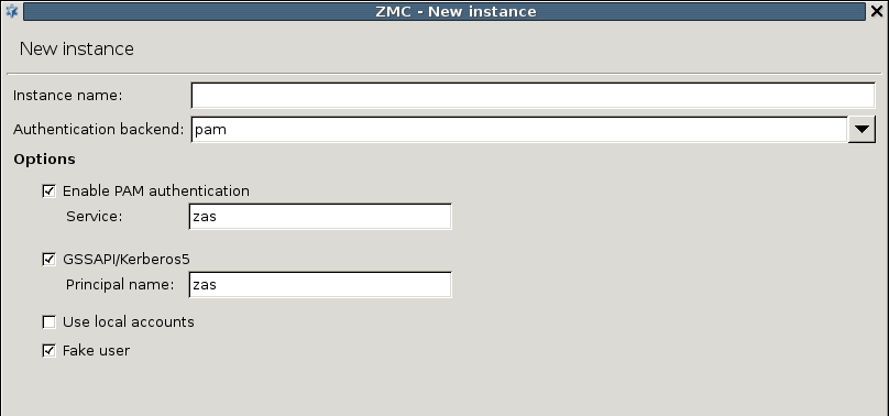
The PAM backend implements authentication based on the local authentication settings of the host running AS. It basically authenticates the users against the local PAM installation and/or using GSSAPI/Kerberos5. The PAM backend has the following parameters:
: Enable PAM authentication. For PAM authentication the PAM service used for authentication has to be specified.
: Enable GSSAPI based authentication. The representing this authentication service also has to be set.
: Use the local passwd/group database to query group membership of a given account.
Authentication faking can be enabled by selecting the checkbox.
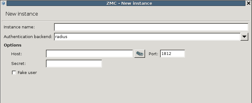
Routers are simple conditional rules (that is, if-then expressions) that determine which instance has to be used to authenticate a particular connection. They consist of a condition and a corresponding instance: if the parameter of the connection matches the set condition, then the authentication is performed with the set instance. The condition consists of a variable and a pattern: the condition is true if the variable of the connection is equal to the specified pattern. Routers can be configured in the section of the MC component. They are evaluated sequentially: if the incoming connection matches a router, authentication is performed according to the instance specified in the router, otherwise the next router is evaluated. Configuring a new router is very simple, only the condition has to be specified and the backend instance selected. The exact procedure is as follows:
-
Navigate to the MC component, and click in the section of the tab.
-
Select the instance that will authenticate the connections matching this router from the combobox.
-
Click on , and define a condition for the router. Select the variable to be used from the combobox, and enter the search term to the field. If the of the inspected connection matches , the instance specified in will authenticate the connection.
Currently the following variables can be used to create conditions:
Client IP,Client zone,Service, andUser.
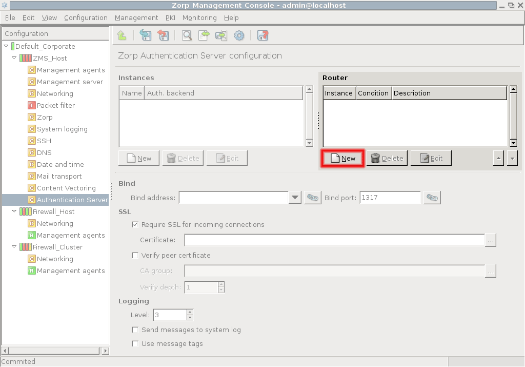
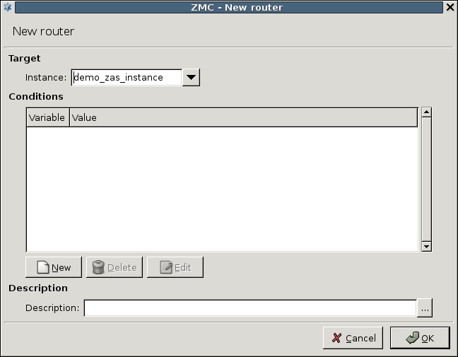
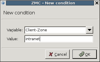
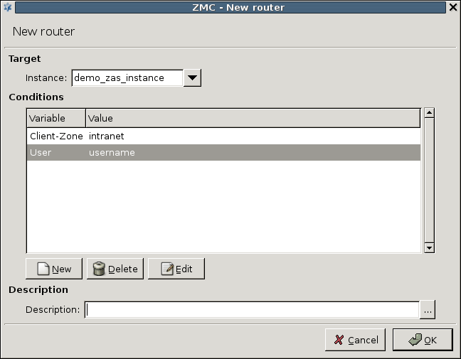
AS can only authenticate connections for which PNS services explicitly request authentication. To allow this, the connection between PNS and AS has to be set up. This requires configuring some connection parameters both in PNS and in AS. The procedure below describes how to configure these parameters.
15.3.2.1. Procedure – Configuring communication between PNS and AS
-
First, the connection settings of AS have to be configured in the section on the MC component. Specify the IP address/port pair on which AS should accept connections.
Tip If AS and PNS are running on the same machine, use the local loopback interface (IP:
127.0.0.1).Note The same bind settings will have to be used when the Authentication provider is configured in the tab of the MC component.
-
If PNS and AS are running on separate machines, enable and configure SSL encryption. Check the checkbox and click on next to the textbox and select a certificate. This certificate has to be available on the AS host and will be presented to PNS to verify the identity of the AS server. For details about creating certificates, see Procedure 11.3.8.2, Creating certificates.
To enable mutual authentication (that is, to verify the certificate of PNS), check the checkbox and select the containing the trusted certificates. Also make sure to set the high enough so that the root CA certificate in the CA chain can be verified. The default value (3) should be appropriate for internal CAs.
-
The connection also has to be set up from the PNS side. This can be accomplished by creating an on the tab of the MC component. Click on , select from the combobox, and enter a name for the provider into the textbox.
-
Enter the IP address of the AS server into the field. This must be the same address as specified as for AS in Step 1.
-
If SSL encryption was enabled in Step 2, select the PNS will show to AS. PNS can also verify the certificate shown by AS using the CAs specified in .
Note Obviously, the CAs issuing the certificates of PNS and AS must be members of the CA groups set to be used to perform the verification of the certificates, otherwise the verification will fail.
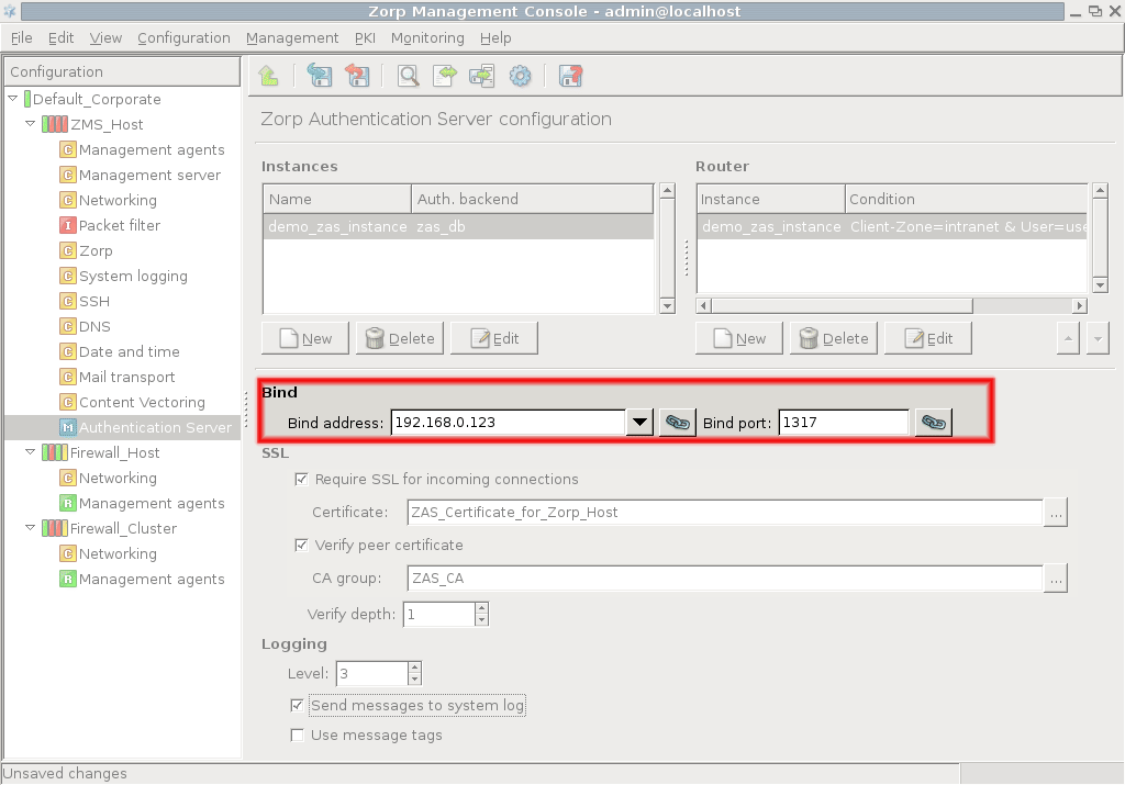
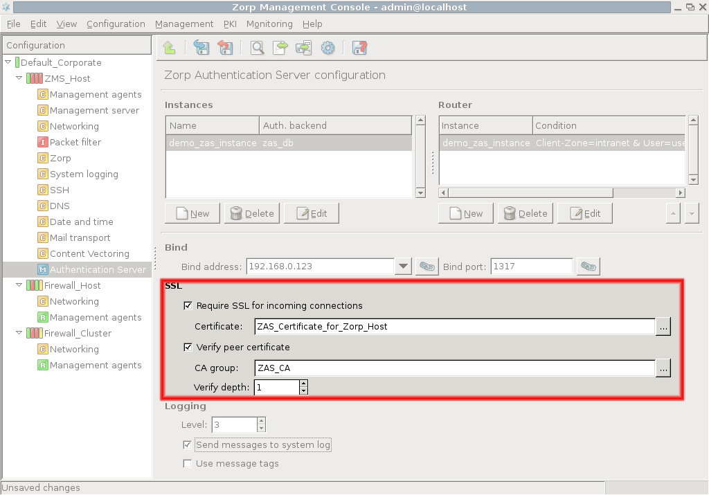
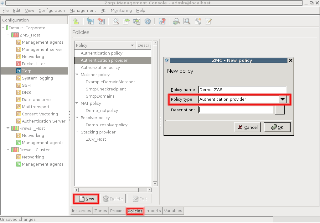
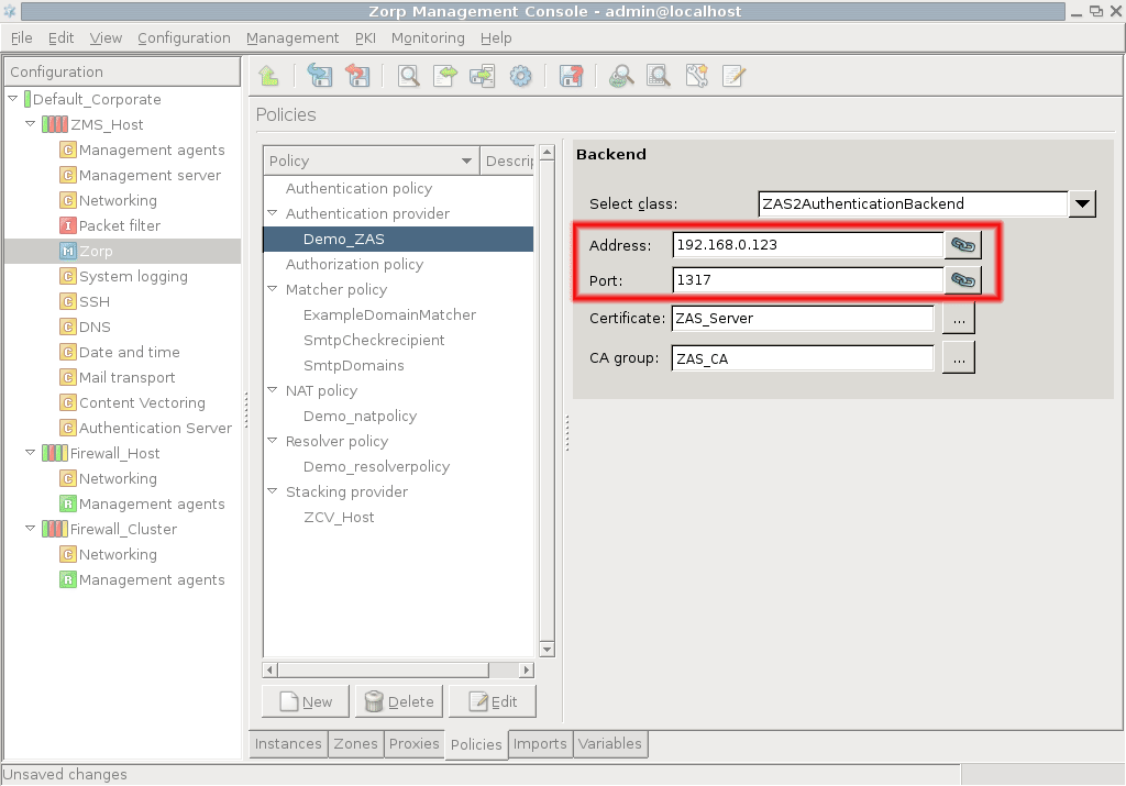
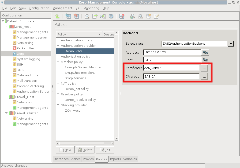
Now an has to be set up. Authentication policies are used by PNS services and specify which authentication provider is used by the service, the type of authentication (inband, outband), and caching parameters. An authentication policy can be used by multiple services.
15.3.2.2. Procedure – Configuring PNS Authentication policies
-
Create an on the tab of the MC component. Click on , select from the combobox, and enter a name for the policy into the textbox.
-
Select the combobox by clicking and selecting a provider.
-
Select the type of authentication to be used from the combobox. The following authentication types are available:
: Use the built-in authentication of the protocol to authenticate the client on PNS.
-
: (Also called Satyr authentication in previous versions). Outband authentication using the Authentication Agent. This method can authenticate any protocol. For agent authentication the following additional parameters have to be set:
: Select the certificate that PNS will show to the authentication agent running on the client. The certificate is required because the communication between the authentication agent and PNS is SSL-encrypted. The certificate has to be issued by a CA trusted by the authentication agent. The process of installing CA certificates for the authentication agent is described in Chapter 6, Installing the Authentication Agent (AA) in Proxedo Network Security Suite 1.0 Installation Guide.
: The port where PNS accepts connections from the authentication agents running on the clients.
: The period of time the client has to complete the authentication after an authentication request is sent by PNS.
: Enable the client to connect to the target server, and extract its authentication information from the protocol.
-
Configure the authentication cache using the combobox of the section. The following options are available:
: Disable authentication caching. The client has to re-authenticate each time when starting a new service.
-
: Store the results of the authentication for the period specified in the field, that is, after a successful authentication the client can use the service (and start new ones of the same type) for that period. for example, once authenticated for an HTTP service, the client can browse the web for period, but has to authenticate again to use FTP.
If the checkbox is selected, timeout measuring is restarted each time the client starts service. Selecting the checkbox means that PNS does not make difference between the different services (protocols) used by the client, after a successful authentication he can use all available services without having to re-authenticate himself. for example, if this option is enabled in the example above, the client does not have to re-authenticate for starting an FTP connection.
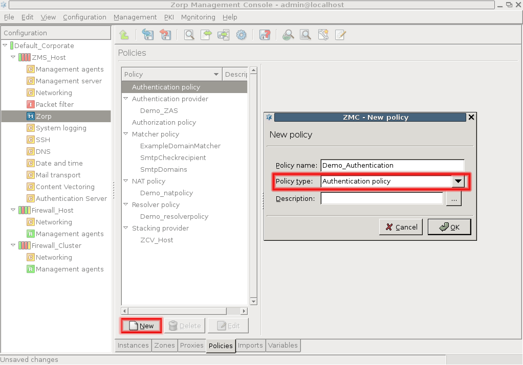
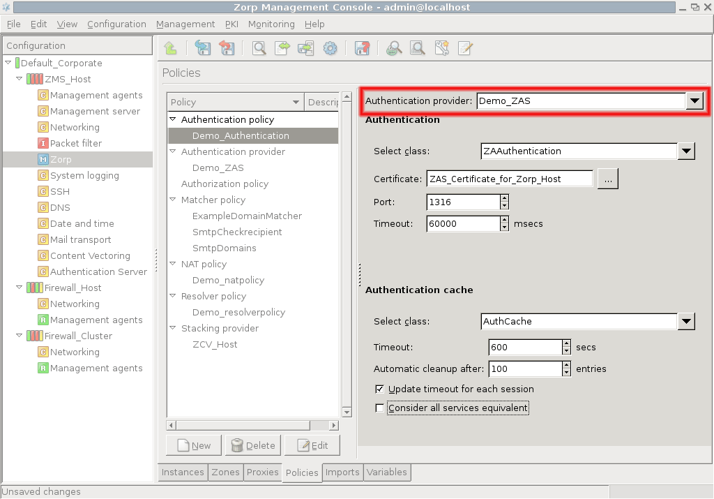
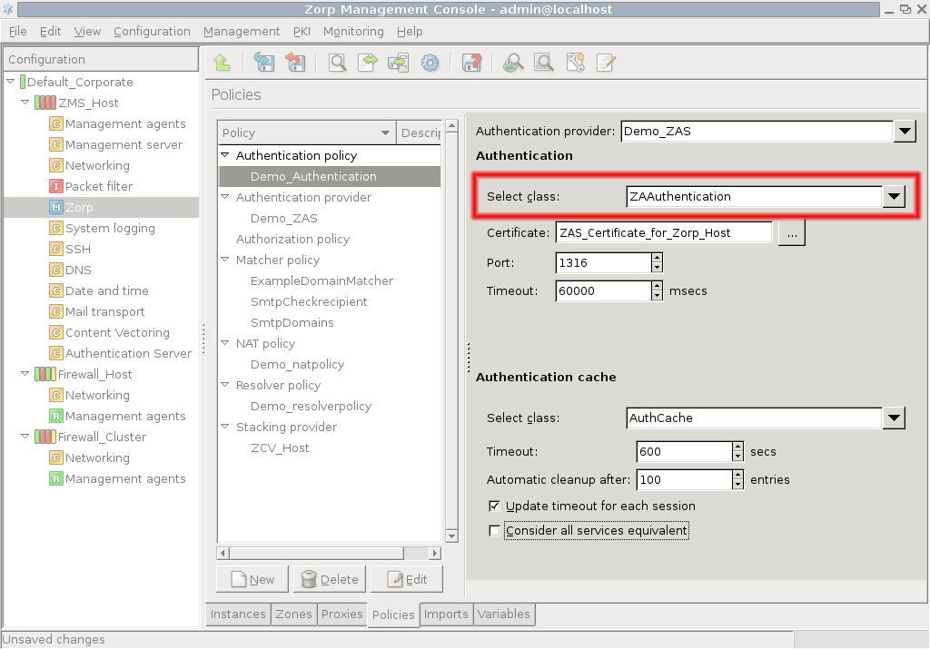
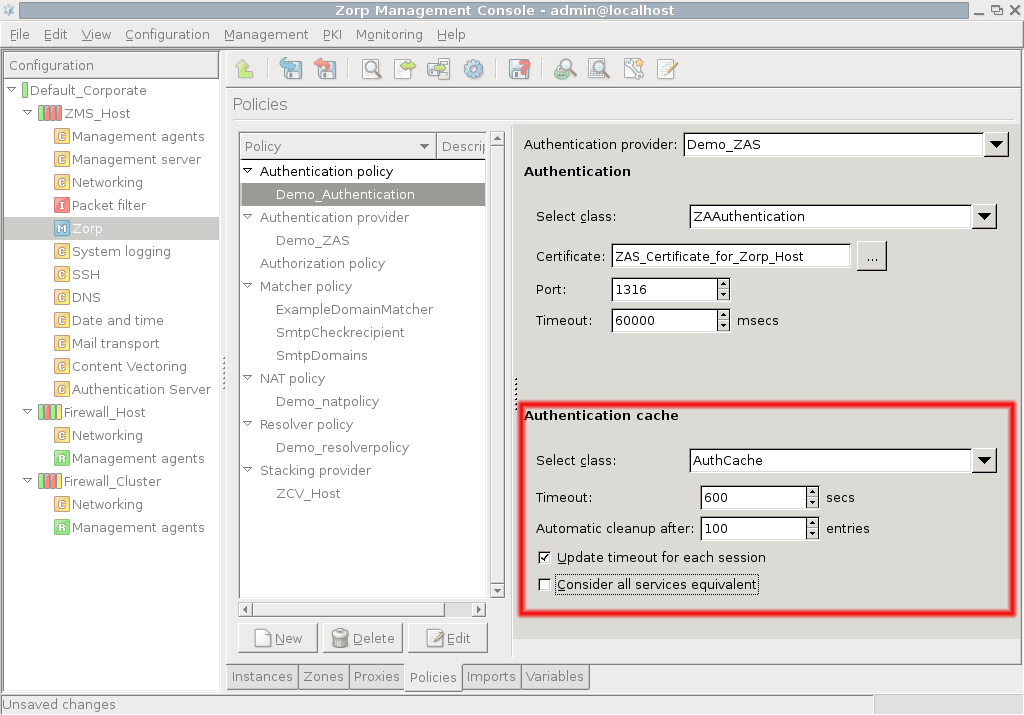
To actually use the authentication policy configured above, the PNS services have to reference the policy.
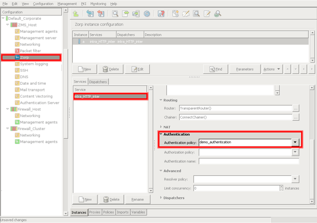
The authentication policy to be used by the service can be selected from the combobox on the tab of the MC component. The combobox displays all the available authentication policies.
Each PNS service can use an Authorization policy to determine whether a client is allowed to access the service. If the authorization is based on the identity of the client, it takes place only after a successful authentication — identity-based authorization can be performed only if the client's identity is known and has been verified. The actual authorization is performed by PNS, based on the authentication information received from AS or extracted from the protocol. PNS offers various authorization models to ranging from simple (PermitUser) to advanced (NEyesAuthorization). Both identity-based and indentity-independent authorization models are available. The configuration of authorization policies is described in the procedure below.
15.3.3.1. Procedure – Configuring authorization policies
-
Create an on the tab of the MC component. Click on , select from the combobox, and enter a name for the policy into the textbox.
-
Select the authorization model to use in the policy from the combobox. The following models are available:
: Authorize only users meeting a set of authorization conditions, for example, certain users, users belonging to specified groups, or any combination of conditions using the other authorization models.
: The client trying to access the service has to be authorized by one (or more) authorized clients. This model can be used to implement 4-eyes authorization solutions.
-
: Authorize only userpairs — single users cannot access a service, that is, only two different users (with different usernames) can access the service.
Tip NEyesAuthenticationandPairAuthenticationare useful when the controlled access to sensitive (for example, financial) data has to be ensured and audited. : Authorize only the members of the listed usergroups. This is a simplified version of the
BasicAccessListmodel.: Authorize only the listed users. This is a simplified version of the
BasicAccessListmodel.-
: Authorize any user but only in the set time interval. This authorization model does not require authentication.
Tip Use the
BasicAccessListauthorization model to combine user authentication with time-based authentication. For example, create a policy consisting of twoRequiredpolicies: PermitTime and PermitUser.
-
Configure the parameters of the selected authorization class. See Section 15.3.3.2, Authorization models of PNS for the detailed description of the classes.
-
Navigate to the tab of the MC component, and select the service that will use the authorization policy.
In the section, select the to use from the combobox.
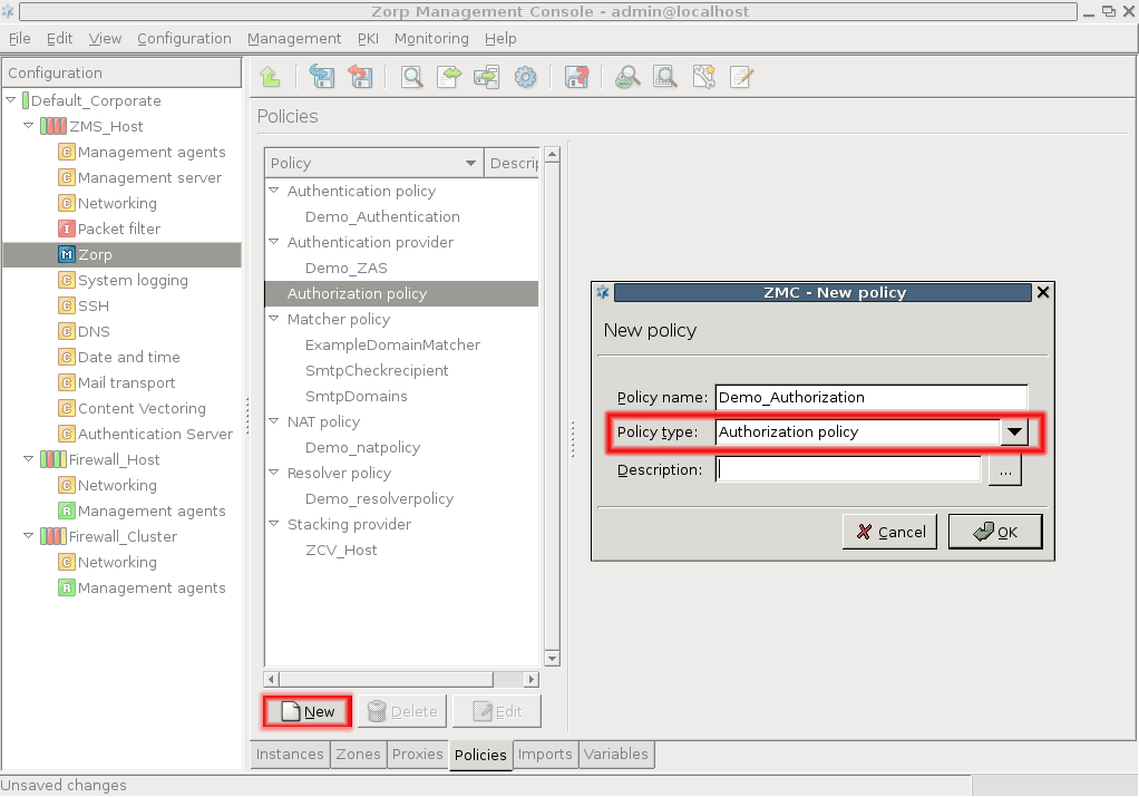
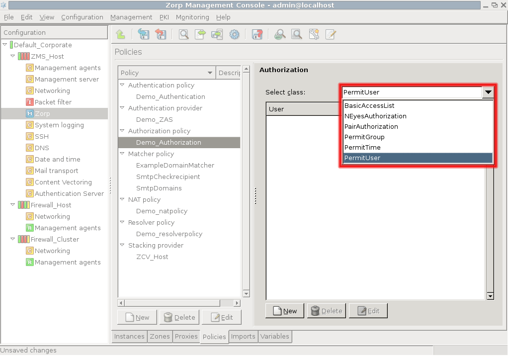
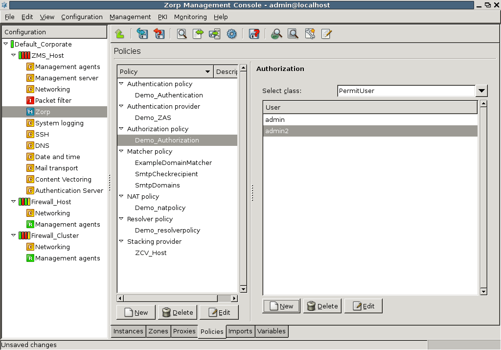
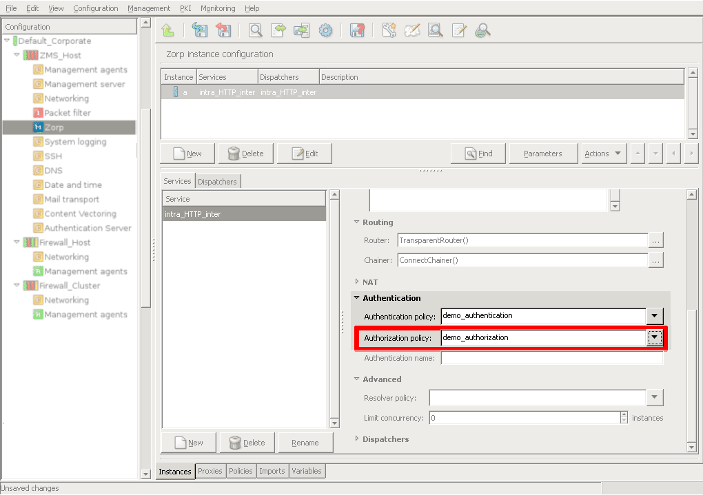
The configuration parameters of the authorization models available in PNS are described in this section.
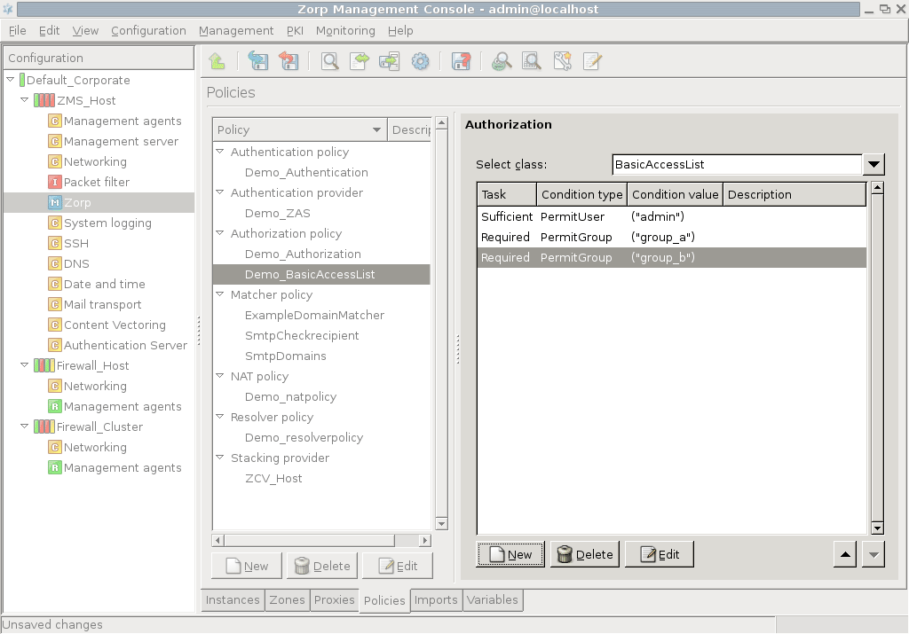
BasicAccessList can be used to create complex authorization scenarios by combining other authorization types into a set of Required or Sufficient conditions. Each condition refers to an authorization type (for example, PermitUser, PairAuthorization, and so on) and (Sufficient or Required). The conditions are evaluated sequentially. A connection is authorized if a Sufficient condition matches the connection, or all Required conditions are fulfilled. If a Required condition is not met, the connection is refused.
| Note |
|---|
Because of the sequential evaluation of the conditions, |
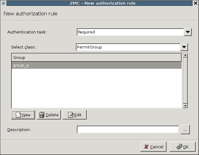
To create a new condition click , and select the type of the condition from the and comboboxes. Then click on , and enter the value for the condition (for example, the username or the name of the group).
When NEyesAuthorization is used, the client trying to access the service has to be authorized by another (already authorized) client (this authorization chain can be expanded to multiple levels). NEyesAuthorization can only be used in conjunction with another NEyesAuthorization policy. One of them is the authorizer set to authorize the authorized policy.
In a simple 4-eyes scenario the authorizer policy points to the authorized policy in its Authorization policy parameter, and has its Wait for other authorization policies to finish parameter disabled. The authorized policy has an empty Authorization policy parameter (meaning that it is at lower the end of an N-eyes chain), and has its Wait for other authorization policies to finish parameter enabled, meaning that it has to be authorized by another policy.
NEyesAuthorization has the following parameters:
: The authorization policy authorized by the current
NEyesAuthorizationpolicy.-
: If this parameter is set, the client has to be authorized by another client. If set to
FALSE, the current client is at the top of an authorizing chain.Note When setting this parameter, consider the timeout value set in the client application used to access the server. There is no use in specifying a longer time here, as the clients will time out anyway.
: The time (in milliseconds) PNS will wait for the authorizing user to authorize the one accessing the service.
When this authorization model is used, only two users simultaneously accessing the service are authorized, single users are not permitted to access the service. Set the time (in milliseconds) PNS will wait for the second user to access the service using the Max time for the pair to arrive spinbutton.
When setting this parameter, consider the timeout valuse set in the client application used to access the server. There is no use in specifying a longer time here, as the clients will time out anyway.
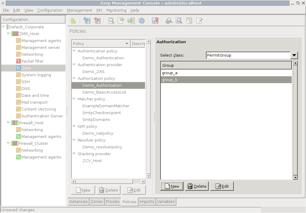
This model allows the members of the specified groups to access the service. Select the grouplist parameter and click . In the appearing list editor window click , then enter the name of an authorized usergroup. Additional groups can be added by clicking again.
| Note |
|---|
The elements of the list can be disabled through the local menu. |
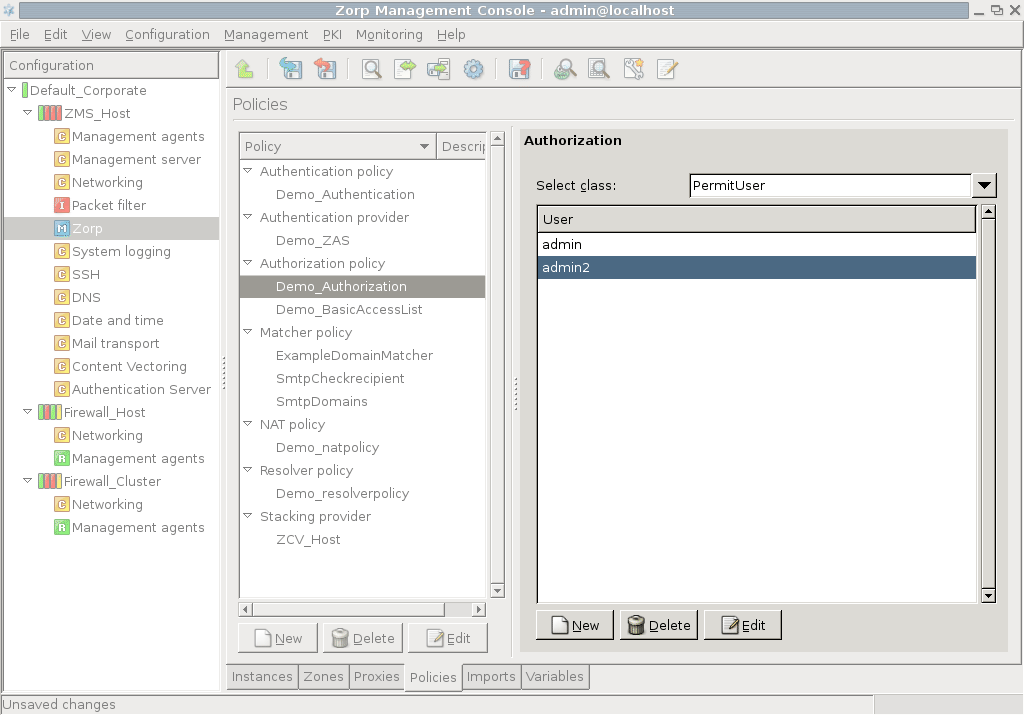
This model allows the listed users to access the service. Select the userlist parameter and click . In the appearing list editor window click , then enter the name of an authorized user. Additional users can be added by clicking again.
| Note |
|---|
The elements of the list can be disabled through the local menu. |
The PermitTime policy stores a set of intervals specified by their starting and ending time — access to a service using such a policy is permitted only within this interval.
To configure an interval, click on , then click . Select the first qstring value and click on . Enter the starting time of the interval (for example, 8:30) and click . The ending time of the interval can be set similarly through the second qstring value.
| Note |
|---|
A single policy can contain multiple intervals. |
The Authentication Agent has to be installed on the client machines when outband authentication is used on the network. For detailed instructions about how to install the authentication agent, see Chapter 6, Installing the Authentication Agent (AA) in Proxedo Network Security Suite 1.0 Installation Guide and Authentication Agent Manual.
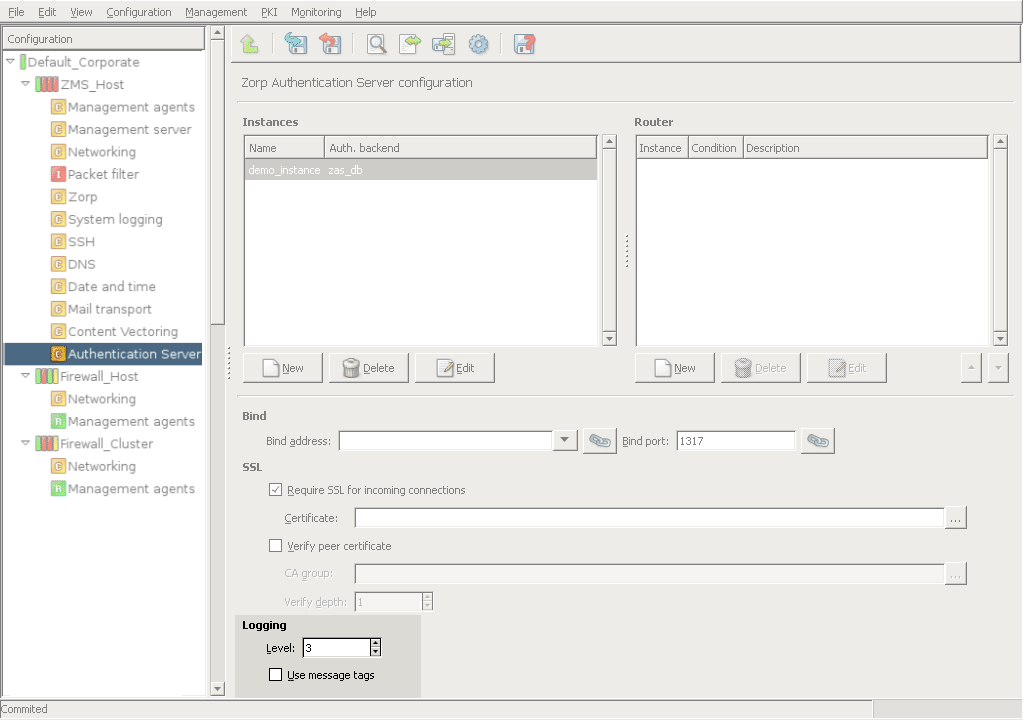
Logging in AS can be configured in the section of the MC component. The parameters related to logging in AS are the following:
: Verbosity level of the logs. Level 3 is the default value, and is usually sufficient. Level 0 produces no logs messages, while 10 logs every small event, and should only be used for debugging purposes.
: Enable the logging of message tags.
This chapter explains how to build encrypted connections between remote networks and hosts using Virtual Private Networks (VPNs).
Computers and even complete networks often have to be connected across the Internet, like in the case of organizations having multiple offices or employees doing remote work. In such situations it is essential to encrypt the communication to prevent anyone unauthorized from obtaining sensitive data. Virtual Private Networks (VPNs) solve the problem of communicating confidentially over an untrusted, public network.
VPNs retain the privacy, authenticity, and integrity of the connection, and ensure that the communication is not eavesdropped or modified. VPN traffic is transferred on top of standard protocols over regular networks (for example, the Internet) by encapsulating data and protocol information of the private network within the protocol data of the public network. As a result, nobody can recover the tunneled data by examining the traffic between the two endpoints.
VPNs are commonly used in the following situations:
To connect the internal networks of different offices of an organization.
To allow remotely-working employees access to the internal network.
To transfer unencrypted protocols in a secure, encrypted channel — without having to modify the original protocol.
To secure Wi-Fi networks.
Different VPN solutions use different methods to encrypt the communication. The main VPN types are IPSec, SSL/TLS, PPTP, and L2TP, with each type having many different implementations. PNS supports the following VPN solutions:
IPSec (strongSwan)
SSL (OpenVPN)
The topology of a VPN determines what is connected using the VPN. The basic VPN topologies are the following:
Peer-to-Peer: Connects two hosts. (Also called Point-to-Point VPN.)
Peer-to-Network: Connects a single host to a network. This is the most common VPN topology, regularly used to allow remote workers access to the intranet of the organization. (Also called Point-to-LAN VPN.)
Network-to-Network: Completely connects two subnetworks. This solution is commonly used to connect the local networks of an organization having multiple offices. (Also called LAN-to-LAN VPN.)
In every case, the VPN tunnel is created between two endpoints: the connecting hosts, or the firewall of the connecting network. The IP addresses of the connected networks or hosts can be fix (Fix IP connections) or dynamic (so called Roadwarrior connections). Roadwarrior connections are typically Peer-to-Network connections, where many peers (roadwarrior clients) can access the protected network.
IP Security (IPSec) is a group of protocols that authenticate and encrypt every IP packet of a data stream. IPSec operates at the network layer of the OSI model (layer 3), so it can protect both TCP and UDP traffic. IPSec is also part of IPv6.
IPSec uses the Encapsulating Security Payload (ESP) and Authentication Header (AH) protocols to secure data packets, and the Internet Key Exchange (IKE) protocol to exchange cryptographic keys. IPSec has the following two modes:
Transport mode: Used to create peer-to-peer VPNs. Only the data part of the IP packet is encrypted, the header is not modified.
Tunnel mode: Builds a complete IP tunnel to create Network-to-Network VPNs.
The IPSec implementation used by PNS has two main components. Pluto is a userspace application responsible for the key exchange when building VPN connections. KLIPS is a kernel module that handles the encryption and transmission of the tunneled traffic after the VPN connection has been established.
OpenVPN creates a VPN between the endpoints using an SSL/TLS channel. OpenVPN operates at the TCP layer of the OSI model (layer 4). The SSL channel is usually created using UDP packets, though it is possible to use TCP. Using SSL enables the endpoints to authenticate each other using certificates.
The OpenVPN server can 'push' certain parameters to the clients, for example, IP addresses, routing commands, and other connection parameters. OpenVPN transfers all communication using a single IP port.
The connecting clients receive an internal IP address, similarly to DHCP. This IP address is valid only within the VPN tunnel, and usually belongs to a virtual subnet.
OpenVPN creates VPN tunnels between virtual interfaces. These interfaces have internal IP addresses that are independent from the IP addresses of the physical interfaces, and are visible only from the VPN tunnels.
OpenVPN runs completely in userspace; the user does not need special privileges to use it. The kernel running on the host must support the virtual interfaces used to create the VPN tunnels.
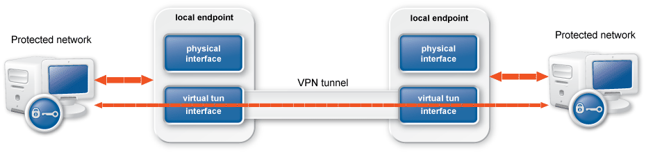
VPN connections can be configured using the MC component. Before starting to configure VPN connections, add this component to the host (see Procedure 3.2.1.3.1, Adding new configuration components to host for details).
| Note |
|---|
If you want only to forward IPSec traffic without terminating the tunnel on PNS, see Procedure 16.3.3, Forwarding IPSec traffic on the packet level. |
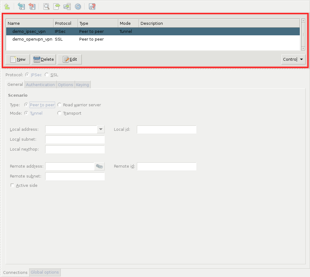
Use the , , and buttons to create, remove, or rename VPN connections. Clicking on displays a drop-down menu to start, stop, or restart the selected connections.
The VPN MC component automatically creates the required ipsec and tun interfaces for the configured VPN tunnels. Use these interfaces to define PNS services that can be accessed through the VPN tunnel. Firewall rules can use these interfaces like a regular, physical network interface. The general procedure of using VPNs is as follows:
16.2.1. Procedure – Using VPN connections
Create the certificates required for authentication using the PNS PKI. See Procedure 11.3.8.2, Creating certificates for details.
-
Configure the VPN tunnel using the VPN MC component. See Section 16.3, Configuring IPSec connections and Section 16.4, Configuring SSL (OpenVPN) connections for details.
Tip To create Peer to Peer or Network to Network connections, use IPSec.
To create Roadwarrior servers, use SSL.
Create services that can be accessed from the VPN tunnel using the PNS MC component.
Configure the remote endpoints (for example, roadwarrior clients) that will access the VPN tunnel. This process may involve installing VPN client software and certificates, and so on.
This section explains how to configure IPSec VPN connections.
16.3.1. Procedure – Configuring IPSec connections
-
Navigate to the VPN component of the PNS host that will be the endpoint of the VPN connection. Select the tab.
Click and enter a name for the connection.
Select the protocol option.
-
On the tab, set the VPN topology and the transport mode in the section.
To create a Peer-to-Peer connection, select the and the options.
To create a Peer-to-Network connection, select the and the options.
To create a Roadwarrior server, select the and the options.
To create a Network-to-Network connection, select the and the options.
Note When creating a Network-to-Network connection, the two endpoints of the VPN tunnel do NOT use the VPN to communicate with each other. To encrypt the communication of the endpoints, create a separate Peer-to-Peer connection.
-
Configure the local networking parameters. These parameters affect the PNS endpoint of the VPN connection. Set the following parameters:
: Select the IP address that PNS will use for the VPN connection.
: The ID of the PNS endpoint in the VPN connection. Leave this field blank unless you experience difficulties in establishing the connection with the remote VPN application. If you set the , you might also want to set the option.
: The IP address of the default network gateway. Packets sent into the VPN tunnel are routed towards this gateway. This parameter defaults to the default gateway used by PNS.
: The subnet or zone protected by PNS that is permitted to use the VPN tunnel, or that can be accessed using the VPN tunnel. This option is available only for Peer-to-Network and Network-to-Network connections.
-
Configure the networking parameters of the remote endpoint. Set the following parameters:
: The IP address of the remote endpoint. Does not apply for roadwarrior VPNs.
: The ID of the remote endpoint in the VPN connection. Leave this field blank unless you experience difficulties in establishing the connection with the remote VPN application. If you set the , you might also want to set the option.
-
: The subnet or zone behind the remote endpoint that is permitted to use the VPN tunnel, or that can be accessed using the VPN tunnel. This option is available only for Peer-to-Network and Network-to-Network connections.
Note Network-to-Network connections connect the subnets specified in the and parameters.
Do not specify the subnet parameter for the peer side of Peer-to-Network connections, leave either the or the parameter empty.
When configuring Peer-to-Peer or Network-to-Network connections, select the option so that PNS initiates the VPN connection to the remote endpoint. If possible, enable this option on the remote endpoint as well.
-
Click on the tab and configure authentication.
To use password-based authentication, select the option and enter the password in the field.
Note Authentication using a shared secret is not a secure authentication method. Use it only if the remote endpoint does not support certificate-based authentication. Always use long and complicated shared secrets: at least twelve characters containing a mix of alphanumerical and special characters. Remember to change the shared secret regularly.
To use certificate-based authentication, select the option and set the following parameters:
: Select a certificate available on the PNS host. PNS will show this certificate to the remote endpoint.
If the remote endpoint has a specific certificate, select the option and select the certificate from the field. PNS will use this certificate to verify the certificate of the remote endpoint.
-
If there are several remote endpoints that can connect to the VPN tunnel, select the option and select the trusted CA group containing the CA certificate of the CA that issued the certificates of the remote endpoints from the field. PNS will use this trusted CA group to verify the certificates of the remote endpoints. (See Section 11.3.7, Trusted CAs for details.)
PNS sends the common name of the accepted CAs to the remote endpoint, so the client knows what kind of certificate is required for the authentication. Select a specific CA certificate using the option if you want to accept only certificates signed by the selected CA.
Note See Chapter 11, Key and certificate management in PNS for details on creating and importing certificates, CAs, and trusted CA groups required for certificate-based authentication.
-
Click on the tab and set the parameter of to
restart. That way PNS attempts to restart the VPN connection if the remote endpoint becomes unavailable.Note Dead peer detection is effective only if enabled on both endpoints of the VPN connection.
-
Set other options as needed. See Section 16.3.2, IPSec options for details.
Note By default, PNS 3 F5 and later uses the IKEv2 key exchange protocol. However, earlier versions support only the IKEv1 protocol. Change the option to IKEv1 when the remote endpoint of the VPN connection is running PNS 3.4 LTS or earlier.
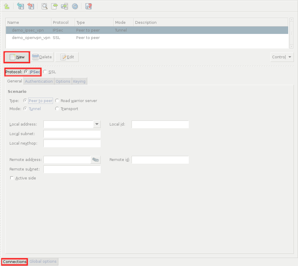
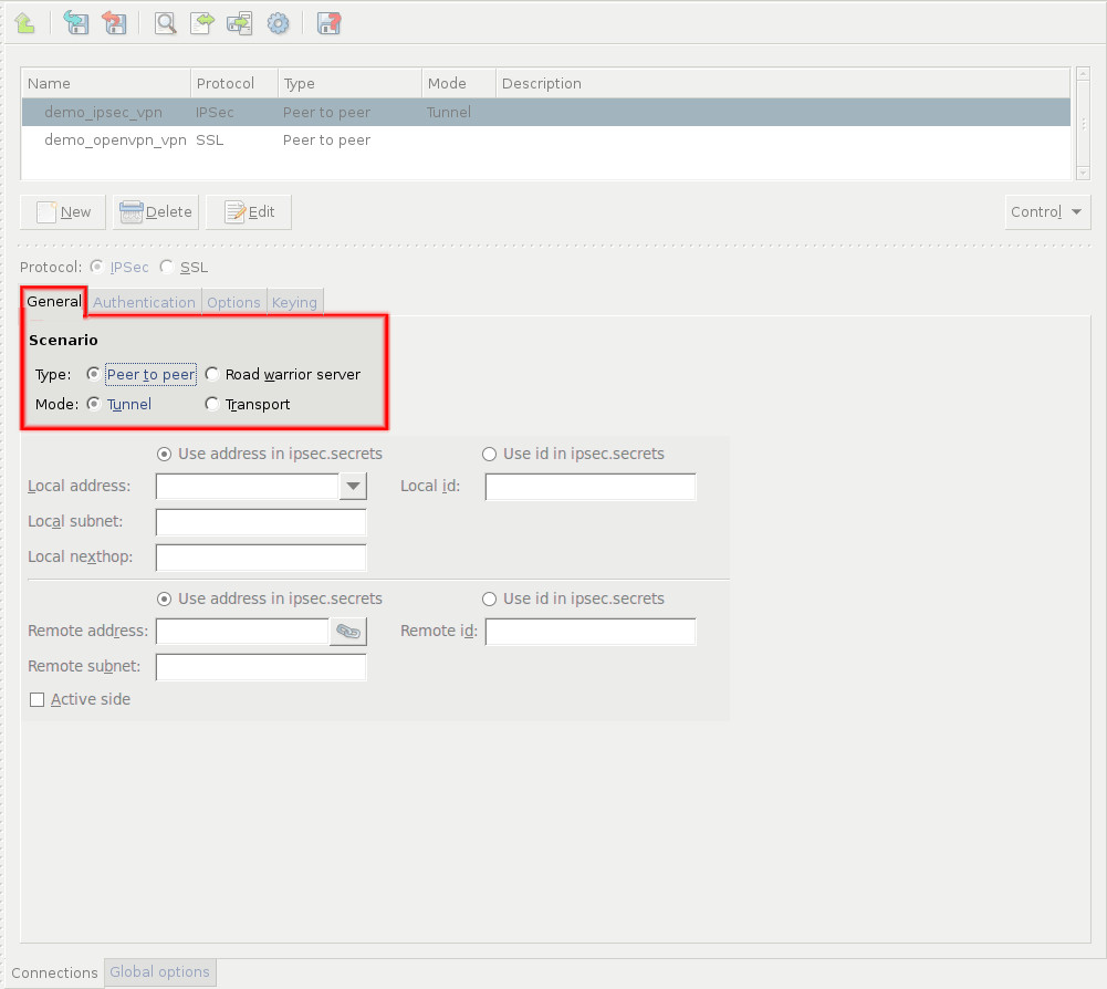
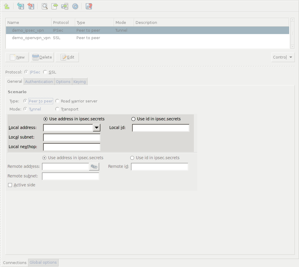
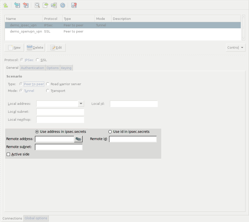
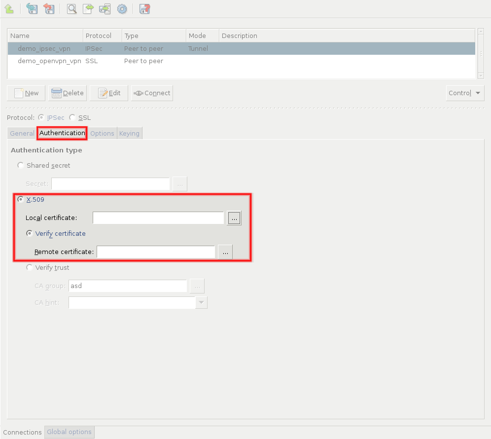
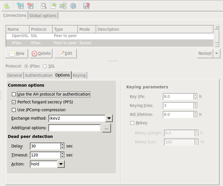
Set special options of a particular IPSec VPN connection on the and tabs. Global parameters that apply to every IPSec VPN connection of the PNS host can be set on the tab.
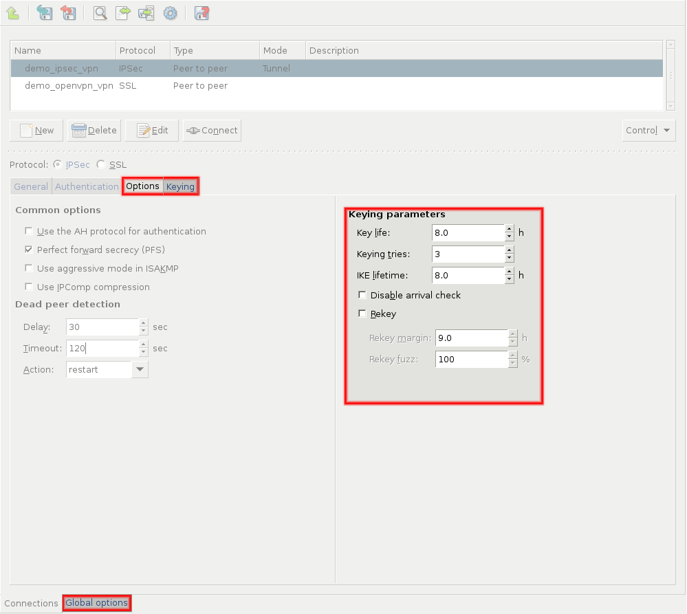
| Note |
|---|
Do not modify these options unless it is required and you know exactly what you are doing. |
The options of the tab specify the encryption used in the connection. The section of the tab specifies key-handling and key-exchange parameters. Modify these parameters only if it is necessary for compatibility with the remote endpoint.
The following options apply to every IPSec VPN tunnel. These settings are available on the tab.
-
: Enable Network Address Translation (NAT) of the encrypted packets. If this parameter is disabled, NAT cannot be used on the encrypted VPN packets, because NAT modifies the header of the packets. Modified packets will be rejected by the remote endpoint, because they were modified by a third party (the device performing the network address translation).
Note Port UDP/4500 is automatically opened if the
Nat Traversalis enabled. : Include log messages of the IKE protocol in the logs.
: If enabled and the VPN interface needs to fragment a packet, then the VPN interface sends a notification to the sender in an ICMP message. This allows the sender to lower its PMTU to avoid packet fragmentation.
: Remove the Type of Service parameter from the tunneled packets.
For details on the other options, see the strongSwan documentation available at http://wiki.strongswan.org/.
16.3.3. Procedure – Forwarding IPSec traffic on the packet level
If you do not want to terminate IPSec traffic on PNS, only to forward such connections, you have to create packet filtering rules for the ESP (protocol number 50) and AH (protocol number 51) protocols. Complete the following steps:
Select the MC component from the configuration tree, and click on the tab.
In the column, open the table, and select the chain.
Click , enter
50into the field, and click . Optionally, you can also specify the source and destination interfacesSelect the chain, click , enter
51into the field, and click .Click .
Commit and upload the configuration changes and reload the Packet filter component.
This section explains how to configure SSL VPN connections.
16.4.1. Procedure – Configuring SSL connections
-
Navigate to the VPN component of the PNS host that will be the endpoint of the VPN connection. Select the tab.
Click and enter a name for the connection.
Select the protocol option.
-
Set the VPN topology in the section.
To create a Roadwarrior server, select the option.
Select the option for other topologies.
Note When creating a Network-to-Network connection, the two endpoints of the VPN tunnel do NOT use the VPN to communicate with each other. To encrypt the communication of the endpoints, create a separate Peer-to-Peer connection.
-
Configure the local networking parameters. These parameters affect the PNS endpoint of the VPN connection.
Set the following parameters in the section:
: Select the IP address that PNS will use for the VPN connection. If PNS should accept incoming VPN connections on every interface, enter the
0.0.0.0IP address.-
: The port PNS uses to listen for incoming VPN connections. Use the default port (
1194) if nothing restricts that.Note These parameters have no effect if PNS is the client-side of a VPN tunnel and does not accept incoming VPN connections.
Set the following parameters in the section:
: The name of the virtual interface used for the VPN connection. MS automatically assigns the next available interface.
: The IP address of PNS as seen from the VPN tunnel. The
tuninterface will bind to this address, so PNS rules can use this address.: The IP address of the remote endpoint as seen from the VPN tunnel.
By default, the VPN connections use the UDP protocol to communicate with the peers. To use the TCP protocol instead, select .
The and addresses must be non-routable virtual IP addresses (for example, from the
192.168.0 0range). These IP addresses are visible only on thetuninterface, and are needed for building the VPN tunnel.Warning The and addresses must be specified even for roadwarrior scenarios. Use the first two addresses of the dynamic IP range used for the remote clients.
-
Configure the networking parameters of the remote endpoint.
For Peer-to-Peer scenarios, set the following parameters:
: The IP address of the remote endpoint.
: The port that PNS connects on the remote VPN server. Use the default port (
1194) if nothing restricts that.: Download the configuration from the remote endpoint. (Works only if the remote endpoint has its push options specified.)
: Select this option if the PNS host that you are configuring should run in client-mode only, without accepting incoming VPN connections.
When PNS acts as a roadwarrior server, set the IP address range using the and fields. Clients connecting to PNS will receive their IP addresses from this range.
Note The configured address range cannot contain more than 65535 IP addresses.
Every Windows client needs a
/30netmask (4 IP addresses). Make sure to increase the available address range when you have many Windows clients. When configuring Peer-to-Peer or Network-to-Network connections, select the option so that PNS initiates the VPN connection to the remote endpoint. If possible, enable this option on the remote endpoint as well.
-
Click on the tab and configure authentication. Set the following parameters:
: Select a certificate available on the PNS host. PNS will show this certificate to the remote endpoint.
: Select the trusted CA group that includes the certificate of the root CA that issued the certificate of the remote endpoint. PNS will use this CA group to verify the certificate of the remote endpoint.
Warning If several remote endpoints use the same certificate to authenticate, only one of them can be connected to PNS at the same time.
Note See Chapter 11, Key and certificate management in PNS for details on creating and importing certificates, CAs, and trusted CA groups required for certificate-based authentication.
-
Configure routing for the VPN tunnel. Click on the tab, and add a routing entry for every network that is on the remote end of the VPN tunnel (or located behind the remote endpoint). PNS sends every packet that target these networks through the VPN tunnel. To add a new network, click , and enter the IP address and the netmask of the network.
-
Configure push options on the tab.
Tip Push options are most often used to set the configuration of roadwarrior clients. For example, it can be used to assign a fix IP address to a specific client.
Click to add routing entries for the remote endpoint. These routing entries determine which networks protected by PNS are accessible from the remote endpoint.
See Section 16.4.2.2, Push options for details.
Set other options as needed. See Section 16.4.2, SSL options for details.
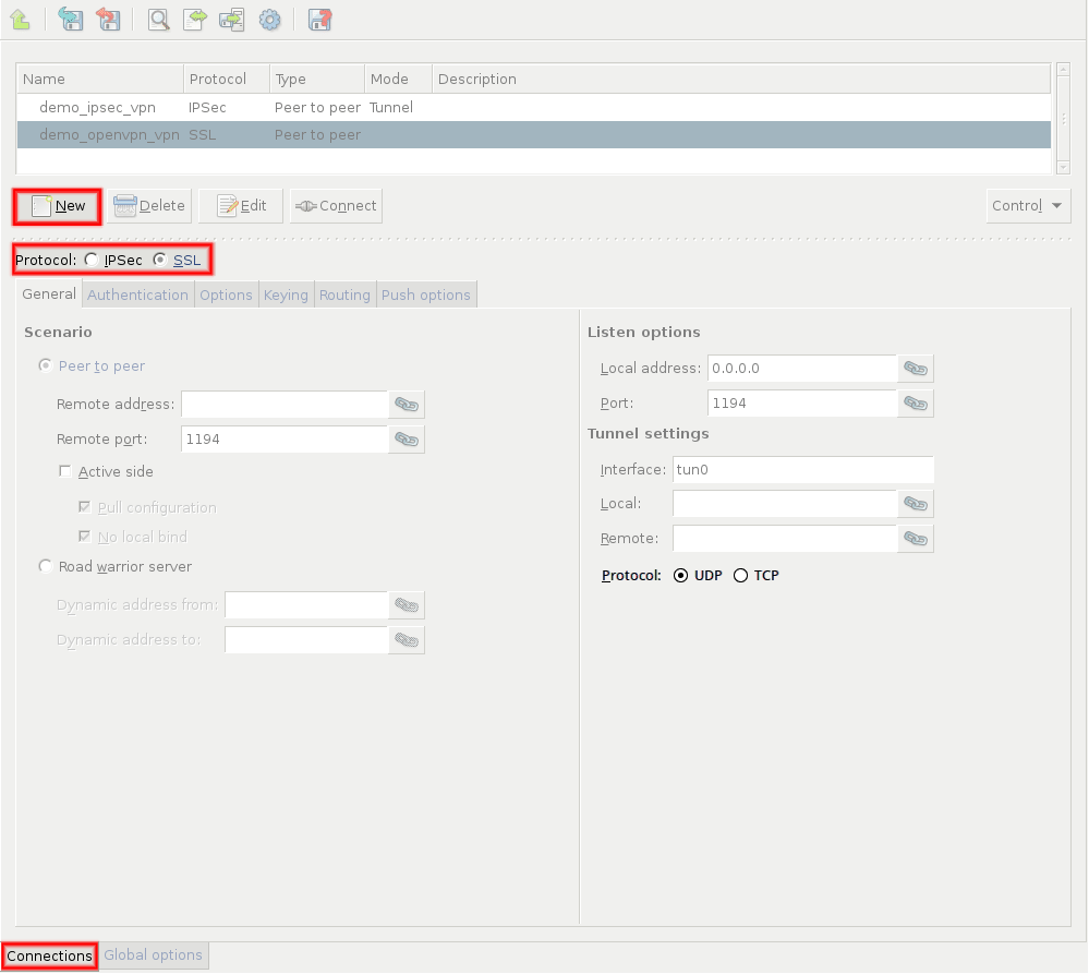
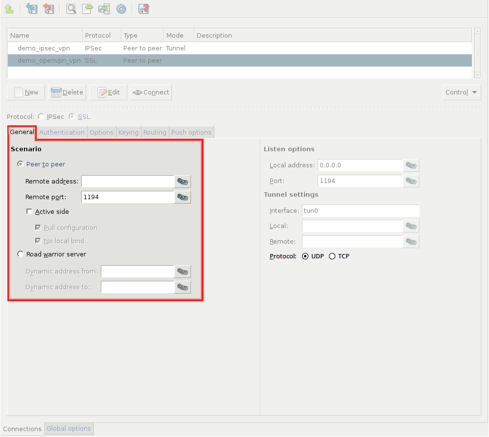
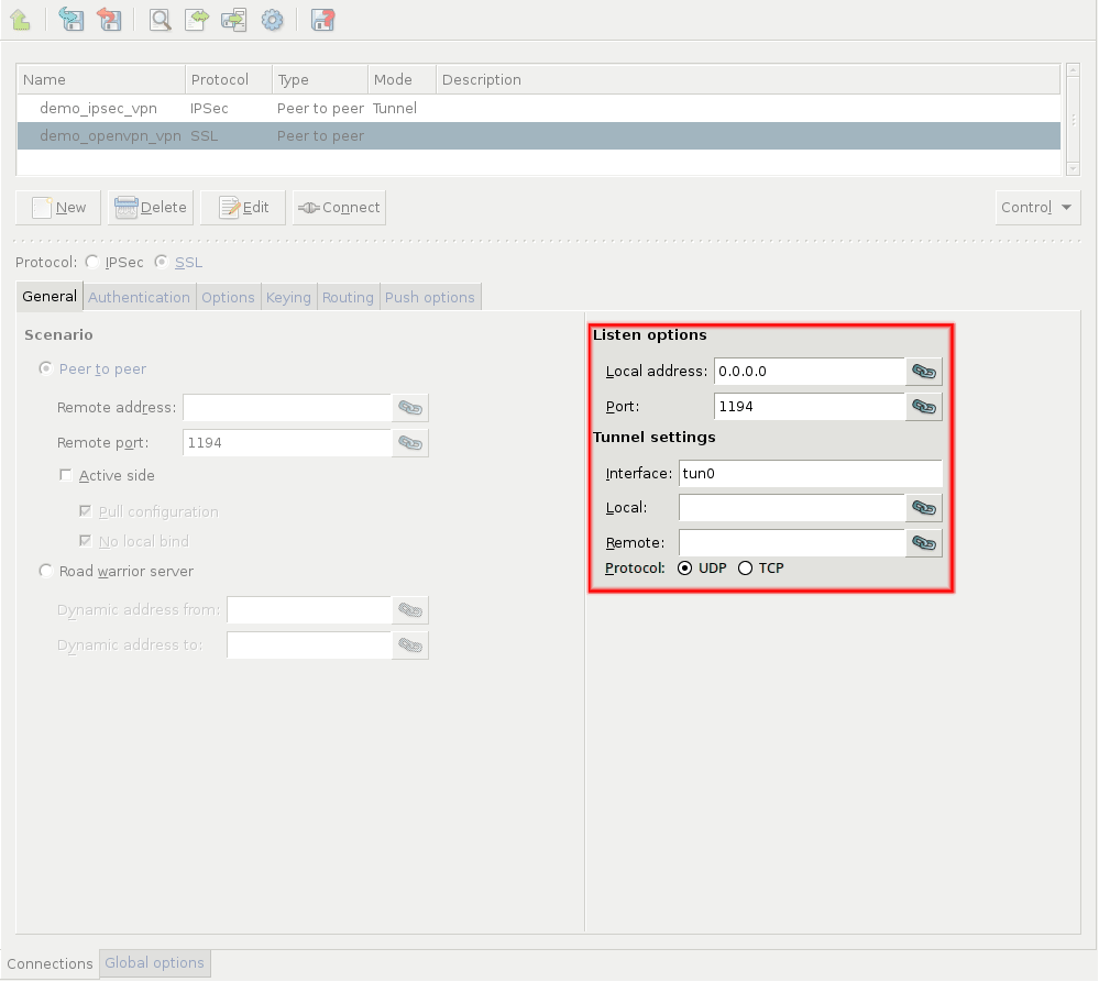
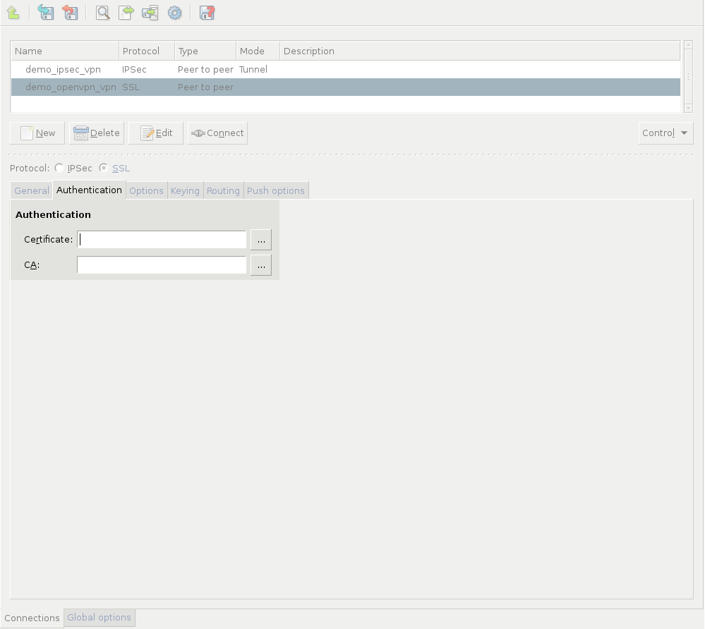
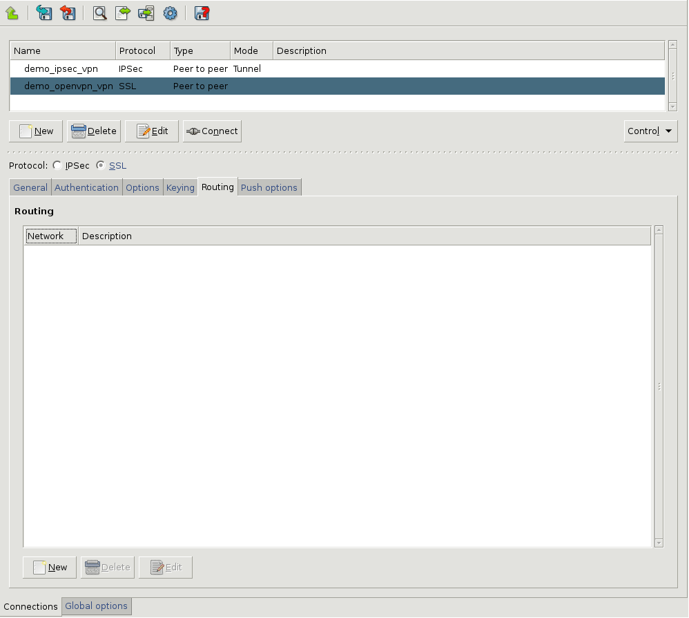
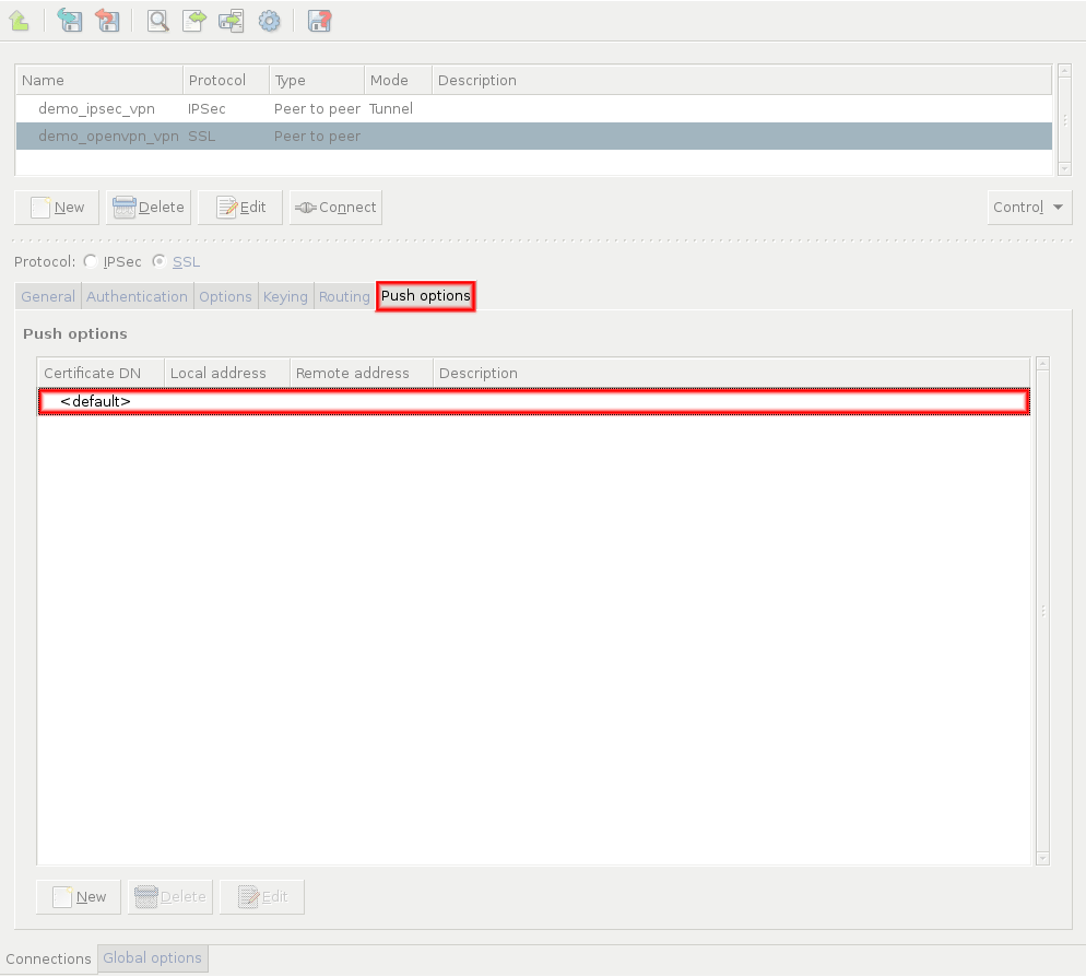
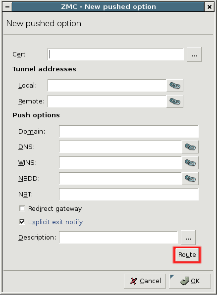
Special options of a particular SSL VPN connection can be set on the and the tabs.
| Note |
|---|
Do not modify these options unless it is required and you know exactly what you are doing. |
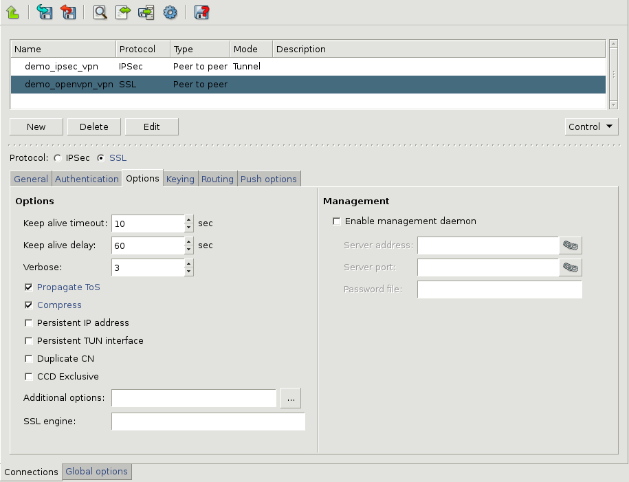
The following options can be set on the tab:
: PNS pings the remote endpoint periodically. This parameter specifies the time between two ping messages in seconds.
: The amount of time in seconds until PNS waits for a response to the ping messages. If no response is received within this period, PNS restarts the VPN connection.
: The verbosity level of the VPN tunnel.
: If enabled and the Type of Service (ToS) parameter of the packet transferred using the VPN is set, PNS sets the ToS parameter of the encrypted packet to the same value.
: Compress the data transferred in the VPN tunnel.
: Preserve initially resolved local IP address and port number across SIGUSR1 or --ping-restart restarts.
: Create a persistent tunnel. Normally TUN/TAP tunnels exist only for the period of time that an application has them open. Enabling this option builds persistent tunnels that live through multiple instantiations of OpenVPN and die only when they are deleted or the machine is rebooted.
: If enabled, multiple clients with the same common name can connect at the same time. If this option is disabled, PNS will disconnect new clients if a client having the same common name is already connected.
: If enabled, the connecting clients must have a
--client-config-dirfile configured, otherwise the authentication of the client will fail. This file is generated automatically if the option is enabled on the tab.: Enter any additional options you need to set here. Options entered here are automatically appended to the end of the configuration file of the VPN tunnel.
: Use the specified SSL-accelerator engine.
The options of the tab specify the encryption used in the connection. Modify these parameters only if it is necessary for compatibility with the remote endpoint.
16.4.2.1. Procedure – Configuring the VPN management daemon
For details on the OpenVPN management interface, see the management-notes.txt file in the management folder of the OpenVPN source distribution.
To enable the management daemon for a particular SSL VPN connection , select the MC component, select the particular SSL connection, and click the tab.
Select .
Enter the IP address where the daemon will accept management connections into the field. It is strongly recommended that IP be set to
127.0.0.1(localhost) to restrict accessibility of the management server to local clients.Enter the port number where the daemon will accept management connections into the field. Note that the IP address:port pair must be unique for every management interface.
Set the path to a file that will store the password to the management daemon. Clients connecting to the management interface will be required to enter the password set in the first line of the password file.
Save your changes and repeat the above steps for other VPN connections if needed.
Push options are settings that the remote clients can download from PNS when the VPN tunnel is built.
To set push options that apply for every remote endpoint of the selected VPN connection, double-click the entry.
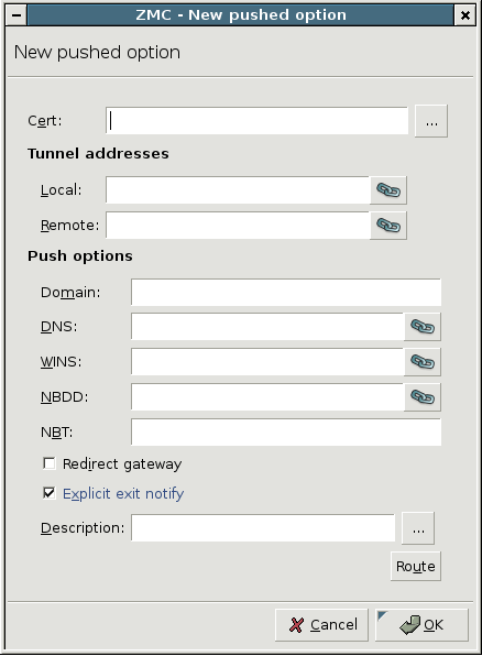
The following push options can be set on the tab:
: The domain of the network.
: Address of the Domain Name Server (DNS).
: Address of the Windows Internet Name Service (WINS) Server.
: Address of the NetBIOS Datagram Distribution (NBDD) Server.
-
: Type of the NetBIOS over TCP/IP node. Enter the number corresponding to the selected mode:
1: Send broadcast messages.
2: Send point-to-point name queries to a WINS server.
4: Send broadcast message and then query the nameserver.
8: Query name server and then send broadcast message.
-
: Sends every network traffic of the remote endpoint through the VPN tunnel. See Section The Redirect gateway option for details.
Note Using the option means that the remote client will have access only to the services permitted by PNS for the VPN tunnel when the VPN tunnel is active. For example, the client will not be able to surf the Internet using HTTP if PNS allows only POP3 services for the clients connected using the VPN.
: The remote endpoint sends a message to PNS before closing the VPN tunnel. If this option is disabled, PNS does not immediately notice that an endpoint became unavailable, and error messages might appear in the PNS logs.
: Enter any additional push options you need to set here. Options entered here are automatically appended to the end of the
.ccdfile of the VPN tunnel. This option can be used for example to set theirouteparameter.: Add routing entries for the remote endpoint. These routing entries determine which networks protected by PNS are accessible from the remote endpoint.
To set push options for a specific remote endpoint, click and select the certificate of the remote endpoint.
| Note |
|---|
Alternatively, you can enter the Unique Name of the endpoint certificate into the field. That way, certificates not available in the PNS PKI system can be used as well. |
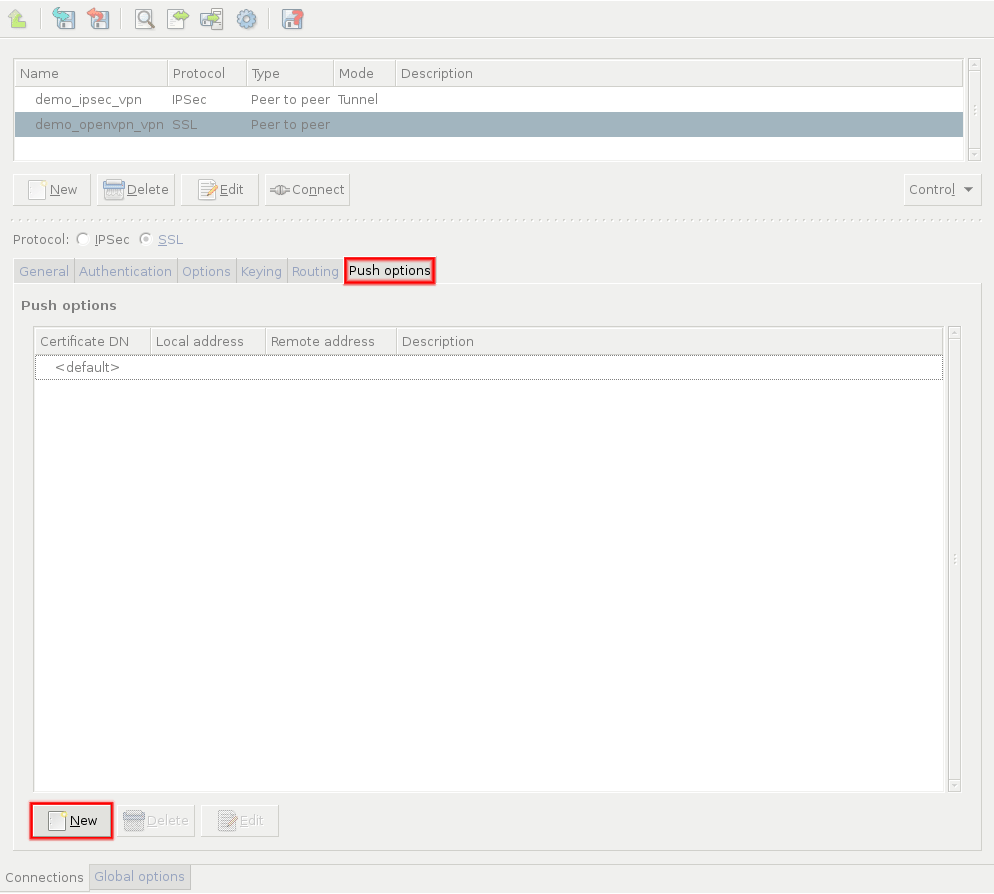
In this case, the IP addresses visible in the tunnel can also be set, so you an assign a fixed IP address to the client using the parameter. Note that the and directions are from the client's perspective: is the remote client's IP address in the VPN tunnel, while is the IP address of PNS in the VPN tunnel.
When assigning fixed IP addresses to Windows clients, remember that every Windows client needs a /30 netmask (4 IP addresses). For every client, use an IP pair of the following list as the last octet of the and IP addresses:
[  1,  2] [  5,  6] [  9, 10] [ 13, 14] [ 17, 18]
[ 21, 22] [ 25, 26] [ 29, 30] [ 33, 34] [ 37, 38]
[ 41, 42] [ 45, 46] [ 49, 50] [ 53, 54] [ 57, 58]
[ 61, 62] [ 65, 66] [ 69, 70] [ 73, 74] [ 77, 78]
[ 81, 82] [ 85, 86] [ 89, 90] [ 93, 94] [ 97, 98]
[101,102] [105,106] [109,110] [113,114] [117,118]
[121,122] [125,126] [129,130] [133,134] [137,138]
[141,142] [145,146] [149,150] [153,154] [157,158]
[161,162] [165,166] [169,170] [173,174] [177,178]
[181,182] [185,186] [189,190] [193,194] [197,198]
[201,202] [205,206] [209,210] [213,214] [217,218]
[221,222] [225,226] [229,230] [233,234] [237,238]
[241,242] [245,246] [249,250] [253,254]
Enabling the push-option overrides the default gateway settings of the remote endpoint and sends every network traffic of the remote endpoint through the VPN tunnel. The remote endpoint can only access the Internet through the VPN tunnel. That way PNS can control what kind of communication (protocols, and so on) can the remote client use while connected to the internal network using the VPN tunnel.
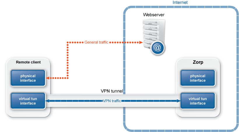
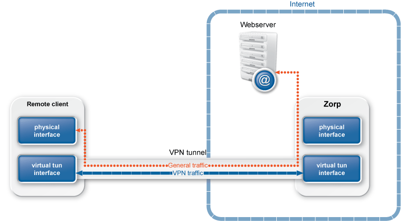
The following flags can be set for the option, with the being set as default:
: Select this option if the end-points of the VPN tunnel are directly connected through a common subnet, such as wireless. Note that in this case PNS does not create a static route for the remote address of the tunnel.
: Select this option to add a direct route to the DHCP server (if it is non-local) which bypasses the VPN tunnel.
: Select this option to override the default gateway by using
0.0.0.0/1and128.0.0.0/1instead of0.0.0.0/0. That way the original default gateway is overridden but not deleted.: Select this option to add a direct route to the DNS server(s) (if it is non-local) which bypasses the VPN tunnel.
Proxedo Network Security Suite 1.0 allows you to monitor the resources of your PNS hosts using external monitoring tools. PNS can be integrated to the following monitoring environments:
17.1. Procedure – Monitoring PNS with Munin
Purpose:
To monitor your Proxedo Network Security Suite hosts with Munin, complete the following steps. Using Munin, you can monitor the memory usage of your hosts, and the number of running processes and threads for your PNS instances.
Steps:
Login to the host locally, or remotely using SSH. For details on enabling SSH access, see Section 9.4, Local services on PNS.
-
Install the required packages using the sudo apt-get install <package-name> command. The package you have to install depends on the role of the host.
For PNS hosts, install the
zorp-pro-munin-pluginspackage.For MS hosts, install the
zms-munin-pluginspackage.For CF hosts, install the
zcv-munin-pluginspackage.If a host has multiple roles, install every applicable package. For example, if MS and CF are running on the same host, install the
zms-munin-pluginsandzcv-munin-pluginspackages.
Install the
munin-nodepackage and configure it as needed for your environment. For details, see the Munin documentation.Login to your MS host using MC, and enable access to the
TCP/4949port. For details, see Section 9.4, Local services on PNS.Repeat this procedure for every Proxedo Network Security Suite host that you want to integrate into your monitoring system.
17.2. Procedure – Installing a Munin server on a MS host
Purpose:
If you do not have a separate Munin server, or you do not want to integrate your PNS hosts into your existing Munin environment, you can install the Munin server on a standalone MS host (installing the Munin server on a PNS or CF host is possible, but strongly discouraged). To achieve this, complete the following steps.
Steps:
Login to the host locally, or remotely using SSH. For details on enabling SSH access, see Section 9.4, Local services on PNS.
Install the Munin server and the Lighthttpd webserver packages. The webserver is required to display the resource graphs collected using Munin. Issue the following command: sudo apt-get install munin lighttpd
-
Configure the Munin server and the webserver as needed for your environment. For details, see the documentation of Munin and Lighthttpd.
Warning By default access to the Munin graphs does not require authentication.
Configure Munin and Lighthttpd to use SSL-encryption, and disable unencrypted HTTP access on port 80. Use port 443, or a non-standard port instead.
Login to your MS host using MC, and enable access to the TCP port you configured in the previous step on your MS host. For details, see Section 9.4, Local services on PNS.
17.3. Procedure – Monitoring PNS with Nagios
Purpose:
To monitor your Proxedo Network Security Suite hosts with Nagios, complete the following steps. Using Nagios, you can monitor the memory usage of your hosts, and the number of running processes and threads for your PNS instances, and the expiry of the product licenses and certificates (for details on certificate and license-monitoring, see Procedure 11.3.8.8, Monitoring licenses and certificates).
Prerequisites:
To monitor your Proxedo Network Security Suite hosts with Nagios, you must already have a central Nagios server installed. It is not possible to install the Nagios server on Proxedo Network Security Suite hosts.
Experience in administering Nagios is required.
Steps:
Login to the host locally, or remotely using SSH. For details on enabling SSH access, see Section 9.4, Local services on PNS.
Issue the following command to install the required packages: sudo apt-get install zorp-pro-nagios-plugins nagios-nrpe-server. The
zorp-pro-nagios-pluginspackage installs three scripts; these are automatically configured to run as root, and are listed in the/etc/nagios/nrpe.d/zorp.cfgfile.Login to your MS host using MC, and enable access to the
TCP/5666port. For details, see Section 9.4, Local services on PNS.Repeat this procedure for every Proxedo Network Security Suite host that you want to integrate into your monitoring system.
-
Add the Proxedo Network Security Suite hosts to your central Nagios server, and create services for the hosts. For details, see the documentation of Nagios.
Note Adjust the alerting limits set in the scripts as needed for your environment.
| Note |
|---|
This appendix appeared was a separate chapter in earlier PNS releases. However, as of PNS 3.3, packet filtering and application-level services are handled and discussed together in Chapter 6, Managing network traffic with PNS, therefore manually modifying the packet filtering rules is required only very rarely, and is not recommended unless absolutely needed. Local PNS services are described in Section 9.4, Local services on PNS. |
The key point of the PNS firewall system is the PNS-based application proxy suit. Besides the application layer gateways, the enclosed packet filter also plays a very important role. Although all of the traffic is handled by the PNS proxies the packet filter also performs additional filtering and helps the proxies' work.
This chapter includes a short introduction on packet filter basics and technologies in general and also shows the main concepts of the Linux packet filter framework which is used with PNS. It also covers the commonly used packet filter policy style which is the default of the MS-based configuration. For further reading on the Linux packet filter, see Appendix C, Further readings.
In the world of computer networks each and every connection is based on packets. No communication takes place without packets. So if you want to filter traffic (connections) it is reasonable to filter the packets. Unlike proxies, packet filters operate with packets on the packet level. If the firewall drops the packets it would result in the drop of the connection.
| Note |
|---|
|
Packet filtering rules are created and managed automatically by MS. Usually it is not required nor recommended to modify them manually. If you want to transfer traffic without application-level inspection, create a packet filter service (see Procedure 6.4.1, Creating a new service for details). To enable access to services running on firewall hosts (e.g., SSH access), see Section 9.4, Local services on PNS. Typically you have to modify the packet filtering rules when you want to forward a traffic without terminating it on Application-level Gateway, like forwarding IPSec VPN connections. |
As packet filters work with individual packets a decision is needed for each and every packet whether that specific packet can pass or should undergo some other action. Packet filters can work with incoming and outgoing packets as well, but the basic decision making procedure is the same. The basic steps of packet filtering are the following.
-
The filter system inspects the packet. It usually checks the following information in the packet header:
source/destination IP addresses,
IP options,
TOS/TTL fields,
source/destination port numbers,
TCP flags,
data part of packet,
and others.
Stateful packet filters can check the state of the given packet related to the known connections (whether this packet belongs to an already seen connection or it is a new packet or it is a packet related to an already established connection, like an ICMP control packet), or to other stateful information (whether this packet fits in the TCP window of the connection). This information provide the basis for the decision. Of course, the firewall can check whether the packets checksum and packets in general are adequate.
-
After inspecting the packet and collecting stateful information, the packet filter evaluates the policy for the given packet. The policy and the representation of the policy might be different between various implementations, but usually Access Control Lists (ACL) are used. ACLs are checked from the top of the list to the bottom. The list entries are usually called rules and these rules are evaluated after one another.
A rule usually contains a match and a verdict part. The match part is evaluated based on the information gathered from the packet before the policy check. If a packet matches the rule the rule's verdict is taken for that packet. The various implementations differ in how they run through the list. One stops evaluating at the first match, while others might take the last match's verdict.
-
After evaluating the ACL the packet filter can work with that packet according to the verdict. Usually, every ACL has a default verdict which controls what should happen with the packet if no match occurs. Based on the main security rule a default deny or default drop approach is a good choice, but as usual it depends on the implementation and on the administrator.
There are numerous verdicts, but usually all implementations support the following basic verdicts. The meaning of the verdicts, though, might differ slightly.
-
Accept,
allowing the packet to pass.
-
Deny/Drop,
denying the packet silently meaning that no error packet is sent back to the sender.
-
Reject,
denying the packet with sending back some kind of error packet (ICMP error message or TCP reset packet depending on the situation).
-
To understand, successfully deploy and easily troubleshoot any packet filter firewall you have to understand how the specific implementation handles the packets and how it evaluates its policy. It is also necessary to learn how the policy is represented and how the configuration is constructed. Knowing the deeper details of implementation helps in configuration.
PNS is based on Linux and like most modern operating system it has some kind of packet filter solution. The Linux kernel has had serious filtering capabilities since version 2.0. Since then, the packet filter framework has been rewritten three times to improve its capabilities, features, speed and robustness. The latest packet filter system in Linux is called Netfilter/IPTables since version 2.4.
Netfilter belongs to the family of stateful packet filters and provides packet mangling and connection NATing capabilities as well. Netfilter is designed to be very flexible in configuration to cover all of the possible packet filtering situations. Although in PNS Netfilter plays less significant role, it is necessarily to understand how it handles packets and how the configuration is organized.
Netfilter itself is a framework in the network subsystem of the Linux kernel. It allows packet filtering, network address translation, and various different packet mangling. It is very sophisticated and open enough to be able to satisfy all the potential needs, but it is a framework only. To be able to utilize its capabilities an easily configurable policy layer is required. This can be realized by IPTables which can be found in the kernel as well. IPTables is built on the Netfilter framework and extensively uses it, that is why it is impossible to use IPTables without knowing the basics of the underlying framework.
In real life scenarios, IPTables and Netfilter work very closely together. It is nearly impossible to separate them. From administration point of view, they do not need to be separated. In PNS Netfilter works through the mediation of IPTables. Netfilter/IPTables is built from smaller blocks which cooperate with each other.
The key building blocks of Netfilter and their roles are presented in the following chapters.
All incoming, outgoing and passing packets must go through the TCP/IP stack of the Linux kernel and as Netfilter works with packets, the best way to influence the packet flow is to cooperate with the protocol stack. At some point of the packet flow, the Netfilter framework hooks in to the Linux kernel. These points are called hooks where the stack passes the packet to the framework, which evaluates the policy on the given packet.
Based on the result of the policy evaluation, the framework can response in the following three ways:
gives back the packet to the stack to allow it to be processed further,
gives back a modified packet,
or drops the packet preventing it from further processing.
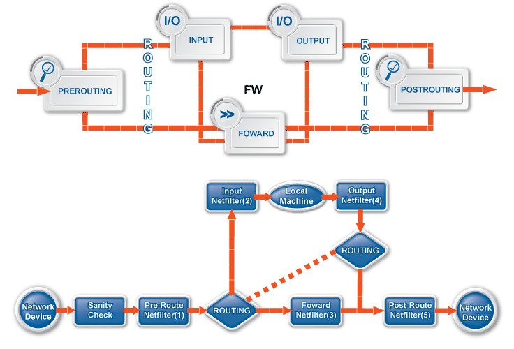
Currently, Netfilter defines five hooks in the kernel.
- PREROUTING
Right after the arrival of the packet from the network and a simple sanity check but before any routing decision is made the packet is sent to this hook.
- INPUT
If the destination of the packet (based on the routing decision) is the host itself, the packet is sent to this hook after the routing decision, but before the delivery of the packet to any application.
- FORWARD
If the destination of the packet (based on the routing decision) is not the host itself and if forwarding is enabled, the packet is sent to this hook after the routing decision, but before leaving the host.
- OUTPUT
If the packet is originating from the host and before any routing decision is made, the packet is sent to this hook.
- POSTROUTING
If the packet is leaving the host and the routing decision is made, the packet is sent to this hook, but before actually passing the packet to the network interface for transmission.
| Note |
|---|
The packet has to pass all of the hooks to get to its destination. It is not enough to pass one hook, all of the hooks must be passed. Obviously, if the packet is dropped on one hook it cannot get to any other hooks. Its processing is ended where it was dropped. |
For example, if the destination of the packet was the host, it has to successfully pass (be accepted) at the PREROUTING and the INPUT hooks. If the destination of the packet was not the host (so it is passing the host) it has to pass at the PREROUTING, FORWARD and the POSTROUTING hooks. The third case is when the packet leaves the box (originating from some application running on the host) it has to pass at the OUTPUT and the POSTROUTING hooks.
These hooks provide the Netfilter framework itself, but they are actually used by IPTables providing the heart of the Linux packet filter system this way.
Hooks only provide an interface where the packets are accessible, but they do not provide a solution to handle the packets. To manage the packets, the Linux kernel provides basically three options which are represented by tables.
-
Filter table,
responsible for Packet Filtering.
-
NAT table,
responsible for Network Address Translation.
-
Mangle table,
responsible for Packet Mangling.
Each table is responsible for one specific action. To fulfil their roles, the tables need to access the packets. Therefore, the tables are registered in the hooks so that they can influence the packet flow in the kernel.
The tables can be configured to carry out other tables' tasks though this solution is not recommended since the tables perform different things and they have different requirements from the hooks, accordingly. Some of the tables cannot be tied to all hooks, but it is also possible that more than one table is involved in one hook. Consequently, more tables can share packets on one hook. Each table can be registered to any hook with a specific priority. The order in which the tables receive the passing packet is based on this priority list.
To successfully pass a hook, the packets have to be accepted on each and every table registered to that given hook. If a packet is dropped by any of the tables it cannot get to the subsequent tables, nor to the subsequent hook.
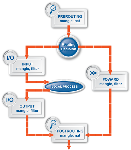
The following tables are involved in packet filtering:
- filter table
-
This table is responsible for the packet filtering, so it represents the classic packet filters. Packets are usually dropped, rejected and accepted here.
This table is registered to the INPUT, FORWARD and to the OUTPUT hooks with the highest priority, meaning that it is the last table which gets the packets at these hooks.
- NAT table
-
This table is responsible for network address translations. Since IPTables is a stateful packet filter, translations occur on the connections not on the packets.
It is important that only the first packet of each connections reaches this table, because one connection can only be NATed once and the selected nat mapping is used for the rest of the packets in the connection.
The nat table is registered to the PREROUTING, POSTROUTING and to the OUTPUT hooks with a lower priority than the filter table, meaning that it receives the packets right before the filter table.
Note Although it is possible to drop a packet at the nat table, it is not recommended, because the filter table is responsible for dropping packets. If a packet is dropped at the nat table it cannot reach the filter table. If a packet is accepted or NATed at the nat table it has to be accepted at the filter table as well to pass.
Basically, two types of NATs are exists: source address, and destination address. They have various special subtypes such as redirect and masquarade. Both NATs can be configured in this table only. Because of the difference between the two NAT types and their influence on the connections, NATs of source type can be configured at the PREROUTING and at the OUTPUT hooks, while NATs of destination type can be configured at the POSTROUTING hook. With careful design, it is possible to translate source and destination NAT on a single specific connection.
- mangle table
-
This table is responsible for various packet mangling like modifying the TTL of the packet, changing the TOS bits, or setting the FWMARK on the packet. This is the table where the biggest alterations take place in the packet and also where serious administration problems can be experienced.
This table is registered to the PREROUTING, INPUT, FORWARD, OUTPUT, and to the POSTROUTING hooks with the lowest priority meaning that it gets the packets first right before the others tables.
The default deny or default drop approach is only partially true in this table. As packet filtering occurs at the filter table the default drop configuration must be utilized only at this table. It is not needed and not possible either to implement a default drop configuration on all tables. If a packet targets a local application or leaves the firewall it has to successfully pass the filter table, so it is enough to drop packets there.
Tip To build a fully functioning configuration, a good approach is to accept all packets on the mangle and on the nat tables and drop all unnecessary packets on the filter table.
Take special care with NATted packets/connections as they appear with their new addresses after the translation so the NATed address must be accepted on the filter table, for example.
Besides the filter, nat and mangle tables another invisible table exists. This table is responsible for connection tracking. IPTables is a stateful packet filter and the statefulness is provided by the connection tracking subsystem which is represented by this table.
This table only checks the relations of the packet towards the connections already investigated. It never drops or rejects any packet, only sets the state information of the packets/connections.
This table is registered to the Prerouting and to the Output hooks with the ever lowest priority meaning it gets the packets before the mangle table.
Using the Netfilter hooks the tables provide the functionalities of the packet filter subsystem in Linux. As tables only provide a container for the policy of a specific functionality, some configuration evaluation system is needed. Like many packet filter implementations IPTables uses ACLs for the evaluation mechanism. While other implementations use only one or a limited number of lists, IPTables can have nearly an infinite number of these. The ACLs are called chains in IPTables.
IPTables chains consists of rules which are evaluated from the top (beginning) of the list to the bottom (end). The evaluation stops at the first matching rule if a verdict is set.
| Note |
|---|
It is possible that a rule does not make a verdict on the packet, in that case the evaluation continues. |
The evaluation can jump to another chain and later can return to the original one, however if the packet matches on any of the chains the evaluations stops. Each chain resides in a specific table and controls the policy of that given table.
There are basically two types of chains.
built-in chains
created chains
Every table contains built-in chains for each of the hooks it has. Every packet that a table on a specific hook gets is put on the specific chain of the given table. The evaluation of this chain is the basis of the verdict of the packet. For example, the filter table has three built-in chains: Input, Forward and Output.
Besides built-in chains, you can create new chains to ease the management of the configuration and can direct the packets on these custom chains by jumping on it.
| Note |
|---|
|
It is possible to jump to a chain in another table. A smart organization of chains makes the configuration easier to understand and makes the evaluation faster. |
The next building blocks of the IPTables configuration are the rules. Tables and chains themselves provide only a container, interface and an evaluation mechanism, but it is the rules that describe the core configuration.
During the evaluation of a chain, actually the rules are evaluated one by one. Every packet is run through this process and the match is checked against each rule in the chains.
The rules consist of two main parts:
match, and
target.
Each packet is tested whether that packet and its related status information is matching the match part of the rule. If a match occurs the target part is used.
| Note |
|---|
|
It is possible that a rule has no target part. In this case nothing happens, only the rules counter is incremented. If a rule has no match part, all packets match that given rule. |
The Netfilter/IPTables system handles matches very flexibly. Almost all aspects of a given packet/connection is possible to be matched. Basically, the matches are just plugins in the framework making it very extendible. Due to the extendibility, a large variety of matches exist.
The match part of a rule can have multiple matches and matching the rule requires that all of the matches are matched. In technical sense, the matches are ANDed together in a rule. If OR-ed matches are required then multiple rules are needed. The most common matches are source/destination address, protocol, source/destination port, TCP flags, connection state (based on the conntrack information), ICMP types and various different mark (FWMARK, CONNMARK) matches. For a full list of matches, see the iptables(8) manpage and the Appendix C, Further readings.
Targets define what should happen with the matched packet. The targets, similarly to the matches are extensions and also behave similarly. Targets can perform two actions:
modify some parameter of the packet/connections (for example, IP addresses, TOS bits, TTLs, MARKs), and
provide a verdict.
| Note |
|---|
|
Not every target has a verdict, meaning that the evaluation of a chain does not end with that matching rule. Remember, the evaluation is ended when a verdict is set, so you need to know which target has a verdict, in other words which one is the final target. For example, the TTL target, which modifies the TTL of the packet cannot ACCEPT it. For ACCEPT, another rule or a default policy is needed. |
Another option for a target is to jump to another chain. In case of jumping to an other chain, the evaluation continues in the new chain. If the other chain is evaluated and no match occurs or no verdict is set, the evaluation continues in the original chain from the next rule after the jump.
The most commonly used targets are ACCEPT, DROP, REJECT, TOS, TTL, [DS]NAT and TPROXY. .
Due to the complexity of the framework, creating configurations with IPTables is a challenging task. For a well-organized and working setup, a very careful design is required. It is very important to use the different tables for their own purposes and to create a working default deny setup.
To make your task easier, MS automatically generates the packet filtering ruleset that of corresponds to the configuration of your PNS Gateways.
| Note |
|---|
|
Packet filtering rules are created and managed automatically by MS. Usually it is not required nor recommended to modify them manually. If you want to transfer traffic without application-level inspection, create a packet filter service (see Procedure 6.4.1, Creating a new service for details). To enable access to services running on firewall hosts (e.g., SSH access), see Section 9.4, Local services on PNS. Typically you have to modify the packet filtering rules when you want to forward a traffic without terminating it on Application-level Gateway, like forwarding IPSec VPN connections. |
MC provides an easy and comfortable way to configure the packet filter system on managed hosts. To configure the packet filter the component must be added to the managed host. The default configuration defines a default deny/drop setup which means that all packets are dropped and logged in the filter table on the INPUT and FORWARD chains since it is enough to disable all passing traffic on the firewall and there is no need to have drop rules on any other chains. By default, the policy permits all outgoing packets.
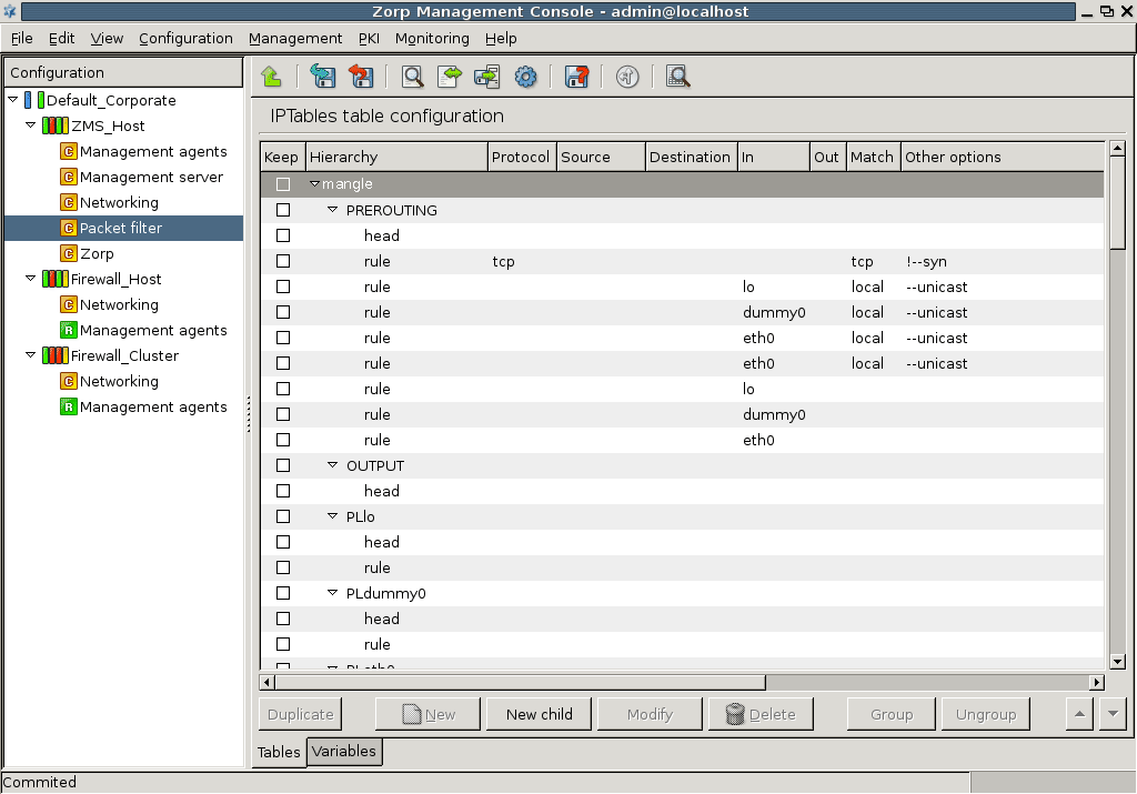
To use the Packet Filter component a basic (but preferably higher) understanding of Netfilter/IPTables is required. This component has three basic purposes:
add/delete/modify rules,
generate configuration, and
search/review the ruleset.
Creating all of the packet filter rules for the firewall and keeping the ruleset in synchrony with PNS is a very challenging and time-consuming task so the to manual configuration is assisted by a feature which generates the ruleset of the policy. Using the generation feature does not raise any boundaries, neither limits the administration nor renders the configuration inflexible. The generated policy is just a skeleton which can be modified as any ordinary ruleset.
The packet filter configuration must be activated on every startup of the firewall or the managed host therefore the configuration is stored in configuration files on the machine. MS uses the iptables-utils package to handle the packet filter configuration. This package is responsible for loading the ruleset upon startup and making the administration easier by using variables. It also prevents accidental lock-out from the box by a misconfiguration. This package is a self-sufficient program and can be used separately from MS.
For managing the configuration, the iptables-utils uses four configuration files.
-
Iptables.conf.varThis file stores the variables which can be used in the policy. These variables are not the same as MS variables and not involved in MS-based configuration.
-
Iptables.conf.inThis file stores the policy itself with unresolved variables.
-
Iptables.conf.newThis file stores the generated configuration from the
iptables.conf.inandiptables.con.varfiles meaning that the variables are resolved here. -
Iptables.confThis file stores the actual configuration. The startup policy is loaded from this file.
Three small utilities are used to manage these files and all of them form part of the iptables-utils package. To generate the iptables.conf.new file iptables-gen util is used. To test the new configuration and to prevent lock-outs iptables-test is needed, which loads the policy from iptables.conf.new, lets it run for 10 seconds and then reloads the old configuration, which is assumed to be functional, from the iptables.conf file. If the configuration is working the new configuration can be made effective with the iptables-commit util, which loads the new configuration and replaces the iptables.conf file.
To control the packet filter system the /etc/init.d/iptables-utils is used. It is the init-script which also loads the configuration policy upon start-up. When starting the utils, it only loads the policy stored in the iptables.conf file. During restart, it generates a new configuration with iptables-gen and attempts to load it. In case any error occurs, it reverts back to the old configuration stored in the iptables.conf file. If it succeeds, it replaces the iptables.conf with the iptables.conf.new. For further information on the iptables-utils, see the manual page of the utility.
During the MS configuration, the iptables-utils creates the iptables.conf.in and the iptables.conf.new files on the managed hosts. Although by default there are no variables used with MS, it is possible to use them. To successfully deploy the new configuration, you have to restart the component in order to regenerate the modified and uploaded configuration.
| Warning |
|---|
|
Without restarting the component, the new configuration is not generated and the modifications are ineffective. If you manually reload iptables rules (that is, using the /etc/init.d/iptables-utils reload command, or the Packet Filter MC component), make sure to reload PNS as well. Otherwise, your packet-filtering services (PFServices) will not function. |
Modifying the ruleset basically means creating new rules/chains, modifying some of their parameters or simply deleting them. This component provides a clean interface for doing these tasks.
| Note |
|---|
|
Packet filtering rules are created and managed automatically by MS. Usually it is not required nor recommended to modify them manually. If you want to transfer traffic without application-level inspection, create a packet filter service (see Procedure 6.4.1, Creating a new service for details). To enable access to services running on firewall hosts (e.g., SSH access), see Section 9.4, Local services on PNS. Typically you have to modify the packet filtering rules when you want to forward a traffic without terminating it on Application-level Gateway, like forwarding IPSec VPN connections. |
The packet filter ruleset can be managed on the tab of the MC component.
The ruleset consists of four basic elements that are organized into a tree. The four elements can be found on different levels of the layout tree.
The root elements are the tables which are fixed and cannot be modified in any way.
-
Each table holds a number of table-specific chains. Both types of chains, built-in and user-defined chains, are on the second level of the tree. Built-in chains cannot be deleted and only their default policy can be modified. To add a new chain to a table, select the table and click . Alternatively, you can select an existing chain of the table and click .
The order of the chains in the table is not important and does not influence the behavior of the ruleset.
The child entries of the chains are the rules. To create a new rule in a chain, select the chain and click . Alternatively, you can select an existing rule of the chain and click . For easier overview and management the rules can be grouped together. Groups and rules that do not belong to any group appear on the third level of the tree. To create a group from the rules, select the rules you want to group, right-click on the selected rules, and select from the local menu.
Rules that belong to a group appear on the fourth level of the tree.
Each rule is represented as a row in the table together with its properties (matches and targets) in the columns. Unlike chains, the order of the rules is important. The order can be changed with the small triangle buttons on the right. To create a rule the matches and the targets needs to be configured. To modify a rule, double click the rule and change the match and target part. The most commonly used matches and the targets can be set on the tab, while other rarely used matches can be configured on the tab.
For further information on the matches and targets, see the iptables(8) manpage and the Appendix C, Further readings.
| Tip |
|---|
The direction of a rule can be changed by selecting from the local menu. |
Packet filter policies can be organized in different ways. You are free to create your own arrangements. The skeleton itself provides only one proved and tested way. Although the skeleton is not necessarily full and ready for use, it can be extended and finetuned to meet the requirements. Of course, there can be situations when the skeleton policy is ready for use without modifications.
In a skeleton-based policy, the generated and user-defined rules are mixed and can function together. Without using skeletons only user-defined rules are exist. Generated rules are either based on information collected from other components, such as Networking, IPSec VPN or Application-level Gateway, or set during the generation of the skeleton.
| Tip |
|---|
You are recommended to configure packet filter function through skeletons. |
| Note |
|---|
UDP port 4500 is automatically opened if the |
The ruleset is generated automatically when the configuration of PNS is modified in a way which affects the packet filter configuration. User-defined rules remain untouched if specified as a keep rule, otherwise the generator removes these rules from the ruleset.
The generator automatically collects the information required to generate the ruleset from the different MC components. After the generator finished, the newly created configuration is presented and can be used the same way as an ordinary user-created configuration.
The new configuration contains both generated and user defined rules.
| Note |
|---|
You are recommended to keep all user-defined rules and regenerate the configuration every time relevant modifications are made. |
Since the skeleton consists of generated and user created rules, the relative order of their relations is very important. The generator creates and modifies chains and rules as well. In every chain which is modified by the generator, the generated rules always come first and user-created rules come only further in the framework. Generation drops those user-created rules which are not marked keep rules. Every other chains are left intact.
The order of the generated rules is not specified, but all of them are placed before the user-created ones. The relative order of the user-created rules are kept during the generations, although all the user-created rules are moved after the generated ones. There are two exceptions: the head group and the catch-all rules.
Every chain modified/touched by the generator has a head group. The role of the head group is to provide a way to insert user-created rules before the generated ones. The head group is a generated group and is placed as the first entry of the chain so every rule which is in the head group of the specific chain precedes all of the generated rules in the chain. The rules in the head group remain in place during the skeleton generation.
Some chains (built-in chains and user-defined ones from the IPTables point of view) have a catch-all rule(s). These rules try to provide a default policy for those chains which need it, for example the chains in the filter table.
The purpose of the catch-all rules is a default policy so they must be at the end of each chain following the user-created rules. No user created rule can follow them. Any rule appended after these catch-all ones are moved forwards during the generation.
For the filter table chains the catch-all rules consist of a LOG and a DROP rules to log the packets before they are dropped. The LOG rule also logs the chain to make it possible to trace where the packet was dropped. These two rules, but especially the DROP rule provides the default drop approach from the packet filter point of view for the host.
The catch-all rule in the mangle table only ACCEPTs the packets. ACCEPTing any packet in any table other than the filter does not necessarily mean letting it pass or allowing it to the application. Accepting packets in the mangle table means that neither the packet nor its associated mark values are modified; the packet is only passed to further processing.
After skeleton generation, the modified chain looks like the following:
Head group at the beginning with the user created rules in preserved order.
Generated rules with an unspecified order.
User-created rules, again, with also a preserved order.
Catch-all rules
This section describes how PNS selects and marks the packets that will be transparently proxied.
| Note |
|---|
In PNS version 3.3FR1 and earlier, this functionality was achieved using the tproxy table. Starting with PNS version 3.4, the tproxy table is not available in PNS. |
As of PNS version 3.4, the PNS Gateway sets a mark on incoming packets that are to be transparently proxied. Every packet having this specific mark is sent to the LO interface using a policy routing rule. PNS uses the highest bit for marking the packets, that is, 0x80000000. In the iptables ruleset of PNS, this means the following rule: -A LOeth0 --match mark --mark 0x80000000/0x80000000 --jump ACCEPT
Therefore, in case you use any marks, make sure that:
you do not use the highest bit for marking; and that
you use the following mask when setting or checking your marks:
/0x7fffffff
When using your own iptables rules to mark packets for transparent proxying, the marks must set the highest bit as well, and set the proper mask, for example, using the --tproxy-mark 0x80000000/0x80000000 iptables option.
Marking the packets is responsible only for redirecting the packets for transparent proxying, no filtering is performed. The marked packets and connections must be ACCEPTed in the filter table as well to make the packet pass and reach their destination which is a dispatcher for transparently proxied packets.
| Note |
|---|
|
By default, PNS directs every packet to the kzorp target in the mangle table. Explicitly accepting packets earlier in the iptables rules provides a way to avoid the kzorp kernel module. To ensure that the selected packets do not reach the kzorp target, add rules to accept the packets to every chain of the mangle table (PREROUTING, FORWARD, POSTROUTING) before the following rule: -A <name-of-the-chain> --jump KZORP --tproxy-mark 0x80000000/0x80000000. You can use zone matches as well to select the packets to accept. |
The filter table is the place where the real filtering takes place so it is very important to understand how and why packets/connections are ACCEPTed or DROPed here.
Every connection that the firewall has to allow must be ACCEPTed here in some way. Basically, three kinds of traffic is handled at the filter table.
incoming
forwarded
outgoing
The generated ruleset allows every outgoing packet, (reply packets are allowed as well), so that OUTPUT chain ACCEPTs every packet. As PNS is an application level solution no packet forwarding takes place, therefore the FORWARD chain DROPs the packets.
This chain has a head group, like all generated chains, which is responsible for spoof protection. See also section Spoof protection. It has the LOG+DROP catch-all rules at the end as well.
| Note |
|---|
You are not recommended to manually configure the packet filter to allow packet forwarding, though it is possible. |
The incoming traffic is basically handled in the INPUT chain and its subchains since the filter table is only meant for filtering (DROPping REJECTing and ACCEPTing) the packets and the connections. As every ruleset generated chain, the INPUT also begins with the head group, which works just as the same as it works in every other places.
After the head group, the evaluation continues with spoof protection, followed by the broadcast chain and noise filtering. Noise filtering is responsible for DROPping every network traffic/packet that is considered junk like broadcast messages or anything else that you want to drop without LOGing it. This filtering takes place in the noise chain which is generated by the ruleset generator. The noise chain begins with a head group and followed by DROP rules dropping (but not logging) packets going to the broadcast address of the network interfaces. As a catch-all rule the chain ends with a RETURN rule which jumps back to the INPUT chain and the ruleset evaluation continues from there.
| Tip |
|---|
|
You are recommended to finetune the noise chain because the requirements and the network junk vary from site to site. If you want to DROP something, add the appropriate DROP rules to the noise chain, but be careful not to DROP anything which is not a junk and should be LOGed later. Remember not to put any rule ACCEPTing any traffic as this rule would ACCEPT it for the filter table. Use RETURN instead as the noise chain is only for DROPping the junk and other rules would interfere the configuration. |
After that, various ICMP packets are ACCEPTed which are RELATED to already established connections. Not every type of ICMP packets are allowed, only those that are needed for the correct and secure operation of the firewall. These are the following:
destination-unreachable(3)
source-quench(4)
time-exeeded(11)
parameter-problem(12)
ICMP packet types are sent as responses for an already established connection by the remote peer indicating some network problem. RELATED means here that only those messages ACCEPTed which are responses for a known connection, messages related to an unknown connection are not ACCEPTed. For further information on RELATED and ICMP types, see Appendix C, Further readings.
After the ICMP rules, the next rule ACCEPTs every packet which belongs to an already ESTABLISHED connection. This way the reply packets for the outgoing connections are ACCEPTed. To track the state and the relation of a packet to the known connections the conntrack table is used. This table assigns a state information to every packet which is checked here.
The defaults group is next, which is responsible for keeping some necessary default rules. There is no need to modify these default rules although it is possible to add other rules. The first rule ACCEPTs every packet that has been marked for transparent proxying. Transparent proxying packets/connections in the mangle table is just redirecting them to the dispatchers (so they can handle transparent traffic), but every packet must be ACCEPTed on the filter table as well, so transparently proxying them on the mangle table is insufficient in this situation. When a connection is marked for transparent proxying, every packet belonging to that connection receives the same tproxy-mark. This way every previously TPROXYed packet can be ACCEPTed with only one rule. Another use of this mark is to flag those packets/connections which are implicitly requested by PNS and ACCEPT them as well with this rule. These connections are usually the secondary connections of traffic proxied by PNS, for example the data channel of an FTP session. When PNS listens for such a connection, it implicitly requests transparent proxying and flagging so there is no need to manually add rules for them — MS automatically generates the required rule into the PREROUTING chain of the mangle table: -A PREROUTING --match socket --transparent --jump MARK --set-mark 0x80000000/0x80000000. Not that it is also needed to allow/ACCEPT these connections on the filter table and this tproxy matching rule realizes that as well.
Altogether, in the defaults group every packet is ACCEPTed which has been already handled (for example, transparently handled packets) or is related to or part of already known connections. Every other packet must be filtered.
The next group is called local_services which is responsible for handling the packet filter configuration of the local or native services. These services can be set as the first step of the ruleset generation. For every service and for every selected zone an ACCEPT rule is generated matching the protocol, the port and the source zone addresses.
Following the local_services group, the routing group can be found. Like in the tproxy table, the rules are divided to subchains based on the incoming interface of the packets. The routing group is the placeholder for such rules that separate the traffic. For each and every interface a LO<interface name> chain exists and the rules in the routing group jump the evaluation to these chains according to the incoming interface and the IP addresses (primary and alias addresses) of the interface pairs. Every further production rule is located in the LO* subchains. Every LO* chain holds the rules that apply to the traffic coming in on the appropriate interface and target the host itself.
| Note |
|---|
The target IP address of the traffic is not necessarily the IP address of the interface, it can be the IP address of any of its alias interfaces. |
The LO* chains begin with the usual head group. After the head group, the rules generated by the ruleset can be found, but the order of the rules is not specified. The information for the rules come from two components: the Application-level Gateway and the VPN.
For every VPN connection, two rules are generated: one for ACCEPTing UDP packets from the remote end of the connection on source and destination port 500 and another rule ACCEPTing ESP (protocol: 50) packets from the remote end of the connection. These rules only allow the encrypted communication everything inside the tunnel, the real payload which comes on the ipsec* interfaces must be filtered separately like any other traffic.
The other rules placed in the LO* chains are generated based on the information from the PNS components. For every non-Transparent dispatcher in PNS an ACCEPT rule is created in one of the LO* chains according to the Address setting of the dispatcher. The configured Address specifies into which sub LO* chain should the rule be placed in.
Each rule ACCEPTs packets to destination ports configured in the Proxy port attribute where the dispatcher listens for connections.
At the end of the INPUT chain, every packet is LOGged and DROPed. Although normally no packet can get to this point of evaluation, because they are thrown to the LO* subchains and at the end of the subchains everything is LOGed and DROPed again. The LOG rule also logs the place (“filter/INPUT”) and the verdict (“DROP”) in the logs.
The purpose of spoof protection is to ensure and enforce that the source address of any packet is in the network which is connected to and reachable through the interface the packet is coming from and only from and through that interface.
| Example A.2. Protection against spoof |
|---|
If a packet comes from the intranet, the source address of the packet must be in the address range of the intranet. If the source address of the packet is in the range of intranet, the packet can only come in on the interface connected to the intranet and from no other interfaces. The last rule is especially important for the internet case where the internet address range (0.0.0.0/0) matches any address, but it must be ensured that the source address does not belong to any other network of the firewall. As the access control of the firewall is based on IP addresses it is very important to be protected against IP spoof attacks. |
However, network topologies can be very complex which renders the spoof protect ruleset very complicated. The ruleset generator automates the generation of these types of rules as well.
To successfully generate a secure ruleset, the generator must be aware of the network topology of the neighbourhood of the firewall. In the Networking component for every interface you have to configure the connected (Connects) zones and set the also.
The connected zones sets which zones, which network addresses are reachable through that interface. The core of the spoof protection is the spoof chain which is in the filter table. The spoof chain is jumped from the INPUT and FORWARD chains as both incoming and forwarded connections must be checked against spoof attacks. The chain begins with the crucial head group followed by the loopback interface handling.
First every packet is ACCEPTed that comes in on the LO interface, then everything is LOGed (with a 'filter/spoof DROP' prefix) and DROPed that has source address in the 127.0.0.0/8 network, but the incoming interface is not LO. Spoof check is done on a per-interface basis. Since all the interfaces are checked separately an SP<interface name> chain is created for each interface.
After the loopback interface check taking place in the spoof chain according to the incoming interface, the evaluation is jumped to the appropriate SP* chain.
| Note |
|---|
Alias interfaces work and behave just like their master interface, so anything configured for an alias interface applies to its master interface as well. |
In the SP* chains spoof attacks are checked based on what was configured in the Network component. Every SP* chains has almost the same ruleset, the rules differ only in their target part. The chains contain one or two rules (depending on whether it is a LOG + DROP or a RETURN rule) for every addresses of zones that are connected to the given interface. Every rule has a network address of a zone as a source match.
The order of the rules are very important. The rules are sorted by the netmask of the source match in descending order. This way the rules with the highest netmask comes first, which also means that the smallest networks are matched first. It is inevitable to have this order to match the tightest network first, otherwise the tighter rules would never match, because the bigger networks would match previously.
The target of a rule depends on whether the zone containing the address of the match is selected as a connected zone for the interface to which the chain applies. If it is selected, the target is RETURN otherwise there are two rules: a LOG and a DROP one.
This ruleset ensures that if a zone is connected to an interface, the source address of packets coming in on that interface must match any networks of the zone. It also ensures that if the zone, which contains the network the packet is sourced from, is connected to any other interface then the packet is not allowed, it would be LOGged and DROPped.
Zones that have no addresses associated with or not connected to any interface are not used and ignored.
| Note |
|---|
To have a full and secure spoof protection ruleset it is very important to set the connected zones, otherwise the spoof protect is incomplete. Do not unset the Spoof protection flag in the |
Adding new rules and generating the ruleset is only one part of the configuration process. During the lifecycle of the firewall you have to review and modify the rules. The Packet Filter component provides a Rule Search window as a tool for searching the ruleset.
The Rule Search window is accessible from the button bar.
A.4.4.1. Procedure – Using Rule Search
-
Click on the
 icon.
icon.A new window appears.
-
Fill in the search fields of the tab and click .
The matching rules are selected from the background in the
Packet Filtercomponent window. -
Configure search-criteria and field interpretation on the tab.
Tip If a search criteria does not match the requested rule(s) check the settings on the tab.
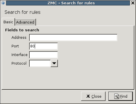
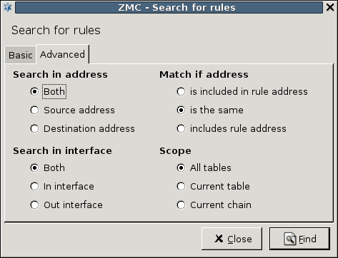
- Ctrl-F1
Display the tooltip of the selected item.
- Shift-F1
Display the help of the selected item.
- F5
Refresh the screen and the status of the displayed objects.
- F8
Activate the splitter bar. Use the cursor keys to resize the selected panel.
- F9
Hide or display the configuration tree.
- F10
Activate the main menu.
- Shift-F10
Display the local menu of the selected item.
- Tab, Shift-Tab
Moves keyboard focus to the next or the previous item.
- Ctrl-Tab, Ctrl-Shift-Tab
Moves keyboard focus to the next or the previous item if Tab has function in the window (for example, in the Text Editor component).
- Ctrl-S
Commit (save) the configuration.
- Ctrl-Shift-E
View the configuration stored in MS.
- Ctrl-E
Compare the configuration stored in MS with the one running on the selected host.
- Ctrl-U
Upload the configuration to MS.
- Ctrl-I
Display the Control Service dialog of the selected component.
- Ctrl-X
Move the selected object to the clipboard.
- Ctrl-C
Copy the selected object to the clipboard.
- Ctrl-V
Paste the object from the clipboard.
- Ctrl-F
Find a keyword in the active list or tree.
- Ctrl-A
Select all objects of the active list or tree.
- Shift-+
Open all objects of the active list or tree.
- Shift--
Close all objects of the active list or tree.
- Shift-+
Open all objects of the active list or tree.
- Shift--
Close all objects of the active list or tree.
- Ctrl-Q
Close MC.
- Esc
Close the active dialog.
Every button, menu item, checkbox, and so on in MC has an access key — an underlined letter in the name of the object. Pressing Alt-<accesskey> activates the object. For example, it selects or unselects the checkbox, or activates the button. For example, Alt-R renames an interface on the component.
The following is a list of recommended readings concerning various parts of PNS administration.
| Note |
|---|
Note that URLs can change over time. The URLs of the online references were valid at the time of writing. |
Guides, manuals, and tutorials for PNS are available at https://docs.balasys.hu/
Author's name. Title. Place of publication: publisher, year. The Postfix Home Page
Blum, Richard. Postfix. SAMS Publishing, 2001. ISBN: 0672321149
Dent, Kyle D. Postfix: The Definitive Guide. O'Reilly Associates, 2004. ISBN: 0596002122
Albitz, Paul, and Liu, Cricket. DNS and BIND. O'Reilly Associates, 2001. ISBN: 0596001584
NTP DocumentationRFC 1305, Network Time Protocol Specification, Implementation and Analysis
Barrett, Daniel J. Ph.D., and Silverman, Richard E. SSH: The Secure Shell The Definitive Guide. O'Reilly Associates, 2001. ISBN: 0596000111
Stevens, W., and Wright, Gary. TCP/IP Illustrated: Volumes 1-3. Addison-Wesley, 2001. ISBN: 0201776316
Mann, Scott. Linux TCP/IP Network Administration. Prentice Hall, 2002. ISBN: 0130322202
Garfinkel, Simson, et al. Practical UNIX and Internet Security, 3/E. O'Reilly Associates, 2003. ISBN: 0596003234
-
The syslog-ng Administrator Guide
(c) IT Security Ltd.
1.1 This License Contract is entered into by and between and Licensee and sets out the terms and conditions under which Licensee and/or Licensee's Authorized Subsidiaries may use the Proxedo Network Security Suite under this License Contract.
In this License Contract, the following words shall have the following meanings:
2.1
Company name: IT Ltd.
Registered office: H-1117 Budapest, Alíz Str. 4.
Company registration number: 01-09-687127
Tax number: HU11996468-2-43
2.2. Words and expressions
Annexed Software
Any third party software that is a not a Product contained in the install media of the Product.
Authorized Subsidiary
Any subsidiary organization: (i) in which Licensee possesses more than fifty percent (50%) of the voting power and (ii) which is located within the Territory.
Product
Any software, hardware or service licensed, sold, or provided by including any installation, education, support and warranty services, with the exception of the Annexed Software.
License Contract
The present Proxedo Network Security Suite License Contract.
Product Documentation
Any documentation referring to the Proxedo Network Security Suite or any module thereof, with special regard to the reference guide, the administration guide, the product description, the installation guide, user guides and manuals.
Protected Hosts
Host computers located in the zones protected by Proxedo Network Security Suite, that means any computer bounded to network and capable to establish IP connections through the firewall.
Protected Objects
The entire Proxedo Network Security Suite including all of its modules, all the related Product Documentation; the source code, the structure of the databases, all registered information reflecting the structure of the Proxedo Network Security Suite and all the adaptation and copies of the Protected Objects that presently exist or that are to be developed in the future, or any product falling under the copyright of .
Proxedo Network Security Suite
Application software Product designed for securing computer networks as defined by the Product Description.
Warranty Period
The period of twelve (12) months from the date of delivery of the Proxedo Network Security Suite to Licensee.
Territory
The countries or areas specified above in respect of which Licensee shall be entitled to install and/or use Proxedo Network Security Suite.
Take Over Protocol
The document signed by the parties which contains
a) identification data of Licensee;
b) ordered options of Proxedo Network Security Suite, number of Protected Hosts and designation of licensed modules thereof;
c) designation of the Territory;
d) declaration of the parties on accepting the terms and conditions of this License Contract; and
e) declaration of Licensee that is in receipt of the install media.
3.1. For the Proxedo Network Security Suite licensed under this License Contract, grants to Licensee a non-exclusive,
non-transferable, perpetual license to use such Product under the terms and conditions of this License Contract and the applicable Take Over Protocol.
3.2. Licensee shall use the Proxedo Network Security Suite in the in the configuration and in the quantities specified in the Take Over Protocol within the Territory.
3.3. On the install media all modules of the Proxedo Network Security Suite will be presented, however, Licensee shall not be entitled to use any module which was not licensed to it. Access rights to modules and IP connections are controlled by an "electronic key" accompanying the Proxedo Network Security Suite.
3.4. Licensee shall be entitled to make one back-up copy of the install media containing the Proxedo Network Security Suite.
3.5. Licensee shall make available the Protected Objects at its disposal solely to its own employees and those of the Authorized Subsidiaries.
3.6. Licensee shall take all reasonable steps to protect 's rights with respect to the Protected Objects with special regard and care to protecting it from any unauthorized access.
3.7. Licensee shall, in 5 working days, properly answer the queries of referring to the actual usage conditions of the
Proxedo Network Security Suite, that may differ or allegedly differs from the license conditions.
3.8. Licensee shall not modify the Proxedo Network Security Suite in any way, with special regard to the functions inspecting the usage of the software. Licensee shall install the code permitting the usage of the Proxedo Network Security Suite according to the provisions defined for it by . Licensee may not modify or cancel such codes. Configuration settings of the Proxedo Network Security Suite in accordance with the possibilities offered by the system shall not be construed as modification of the software.
3.9. Licensee shall only be entitled to analize the structure of the Products (decompilation or reverse- engineering) if concurrent operation with a software developed by a third party is necessary, and upon request to supply the information required for concurrent operation does not provide such information within 60 days from the receipt of such a request. These user actions are limited to parts of the Product which are necessary for concurrent operation.
3.10. Any information obtained as a result of applying the previous Section
(i) cannot be used for purposes other than concurrent operation with the Product;
(ii) cannot be disclosed to third parties unless it is necessary for concurrent operation with the Product;
(iii) cannot be used for the development, production or distribution of a different software which is similar to the BalaSys Product
in its form of expression, or for any other act violating copyright.
3.11. For any Annexed Software contained by the same install media as the Product, the terms and conditions defined by its copyright owner shall be properly applied. does not grant any license rights to any Annexed Software.
3.12. Any usage of the Proxedo Network Security Suite exceeding the limits and restrictions defined in this License Contract shall qualify as material breach of the License Contract.
3.13. The Number of Protected Hosts shall not exceed the amount defined in the Take Over Protocol.
3.14. Licensee shall have the right to obtain and use content updates only if Licensee concludes a maintenance contract that includes such content updates, or if Licensee has otherwise separately acquired the right to obtain and use such content updates. This License Contract does not otherwise permit Licensee to obtain and use content updates.
4.1 Authorized Subsidiaries may also utilize the services of the Proxedo Network Security Suite under the terms and conditions of this License Contract. Any Authorized Subsidiary utilising any service of the Proxedo Network Security Suite will be deemed to have accepted the terms and conditions of this License Contract.
5.1. Licensee agrees that owns all rights, titles, and interests related to the Proxedo Network Security Suite and all of 's patents, trademarks, trade names, inventions, copyrights, know-how, and trade secrets relating to the design, manufacture, operation or service of the Products.
5.2. The use by Licensee of any of these intellectual property rights is authorized only for the purposes set forth herein, and upon termination of this License Contract for any reason, such authorization shall cease.
5.3. The Products are licensed only for internal business purposes in every case, under the condition that such license does not convey any license, expressly or by implication, to manufacture, duplicate or otherwise copy or reproduce any of the Products.
No other rights than expressly stated herein are granted to Licensee.
5.4. Licensee will take appropriate steps with its Authorized Subsidiaries, as may request, to inform them of and assure compliance with the restrictions contained in the License Contract.
6.1. hereby grants to Licensee the non-exclusive right to use the trade marks of the Products in the Territory in accordance with the terms and for the duration of this License Contract.
6.2. makes no representation or warranty as to the validity or enforceability of the trade marks, nor as to whether these infringe any intellectual property rights of third parties in the Territory.
7.1. In case of negligent infringement of 's rights with respect to the Proxedo Network Security Suite, committed by violating the restrictions and limitations defined by this License Contract, Licensee shall pay liquidated damages to . The amount of the liquidated damages shall be twice as much as the price of the Product concerned, on 's current Price List.
8.1. shall pay all damages, costs and reasonable attorney's fees awarded against Licensee in connection with any claim brought against Licensee to the extent that such claim is based on a claim that Licensee's authorized use of the Product infringes a patent, copyright, trademark or trade secret. Licensee shall notify in writing of any such claim as soon as Licensee learns of it and shall cooperate fully with in connection with the defense of that claim. shall have sole control of that defense (including without limitation the right to settle the claim).
8.2. If Licensee is prohibited from using any Product due to an infringement claim, or if believes that any Product is likely to become the subject of an infringement claim, shall at its sole option, either: (i) obtain the right for Licensee to continue to use such Product, (ii) replace or modify the Product so as to make such Product non-infringing and substantially comparable in functionality or (iii) refund to Licensee the amount paid for such infringing Product and provide a pro-rated refund of any unused, prepaid maintenance fees paid by Licensee, in exchange for Licensee's return of such Product to .
8.3. Notwithstanding the above, will have no liability for any infringement claim to the extent that it is based upon:
(i) modification of the Product other than by ,
(ii) use of the Product in combination with any product not specifically authorized by to be combined with the Product or
(iii) use of the Product in an unauthorized manner for which it was not designed.
9.1. The number of the Protected Hosts (including the server as one host), the configuration and the modules licensed shall serve as the calculation base of the license fee.
9.2. Licensee acknowlegdes that payment of the license fees is a condition of lawful usage.
9.3. License fees do not contain any installation or post charges.
10.1. warrants that during the Warranty Period, the optical media upon which the Product is recorded will not be defective under normal use. will replace any defective media returned to it, accompanied by a dated proof of purchase, within the Warranty Period at no charge to Licensee. Upon receipt of the allegedly defective Product, will at its option, deliver a replacement Product or 's current equivalent to Licensee at no additional cost. will bear the delivery charges to Licensee for the replacement Product.
10.2. In case of installation by , warrants that during the Warranty Period, the Proxedo Network Security Suite, under normal use in the operating environment defined by , and without unauthorized modification, will perform in substantial compliance with the Product Documentation accompanying the Product, when used on that hardware for which it was installed, in compliance with the provisions of the user manuals and the recommendations of . The date of the notification sent to shall qualify as the date of the failure. Licensee shall do its best to mitigate the consequences of that failure. If, during the Warranty Period, the Product fails to comply with this warranty, and such failure is reported by Licensee to within the Warranty Period, 's sole obligation and liability for breach of this warranty is, at 's sole option, either:
(i) to correct such failure,
(ii) to replace the defective Product or
(iii) to refund the license fees paid by Licensee for the applicable Product.
11.1. EXCEPT AS SET OUT IN THIS LICENSE CONTRACT, BALASYS MAKES NO WARRANTIES OF ANY KIND WITH RESPECT TO THE Proxedo Network Security Suite. TO THE MAXIMUM EXTENT PERMITTED BY APPLICABLE LAW, BALASYS EXCLUDES ANY OTHER WARRANTIES, INCLUDING BUT NOT LIMITED TO ANY IMPLIED WARRANTIES OF SATISFACTORY QUALITY, MERCHANTABILITY, FITNESS FOR A PARTICULAR PURPOSE AND NON-INFRINGEMENT OF INTELLECTUAL PROPERTY RIGHTS.
12.1. SOME STATES AND COUNTRIES, INCLUDING MEMBER COUNTRIES OF THE EUROPEAN UNION, DO NOT ALLOW THE LIMITATION OR EXCLUSION OF LIABILITY FOR INCIDENTAL OR CONSEQUENTIAL DAMAGES AND, THEREFORE, THE FOLLOWING LIMITATION OR EXCLUSION MAY NOT APPLY TO THIS LICENSE CONTRACT IN THOSE STATES AND COUNTRIES. TO THE MAXIMUM EXTENT PERMITTED BY APPLICABLE LAW AND REGARDLESS OF WHETHER ANY REMEDY SET OUT IN THIS LICENSE CONTRACT FAILS OF ITS ESSENTIAL PURPOSE, IN NO EVENT SHALL BALASYS BE LIABLE TO LICENSEE FOR ANY SPECIAL, CONSEQUENTIAL, INDIRECT OR SIMILAR DAMAGES OR LOST PROFITS OR LOST DATA ARISING OUT OF THE USE OR INABILITY TO USE THE Proxedo Network Security Suite EVEN IF BALASYS HAS BEEN ADVISED OF THE POSSIBILITY OF SUCH DAMAGES.
12.2. IN NO CASE SHALL BALASYS'S TOTAL LIABILITY UNDER THIS LICENSE CONTRACT EXCEED THE FEES PAID BY LICENSEE FOR THE Proxedo Network Security Suite LICENSED UNDER THIS LICENSE CONTRACT.
13.1. This License Contract shall come into effect on the date of signature of the Take Over Protocol by the duly authorized
representatives of the parties.
13.2. Licensee may terminate the License Contract at any time by written notice sent to and by simultaneously destroying all copies of the Proxedo Network Security Suite licensed under this License Contract.
13.3. may terminate this License Contract with immediate effect by written notice to Licensee, if Licensee is in material or persistent breach of the License Contract and either that breach is incapable of remedy or Licensee shall have failed to remedy that breach within 30 days after receiving written notice requiring it to remedy that breach.
14.1. Save as expressly provided in this License Contract, no amendment or variation of this License Contract shall be effective unless in writing and signed by a duly authorised representative of the parties to it.
15.1. The failure of a party to exercise or enforce any right under this License Contract shall not be deemed to be a waiver of that right nor operate to bar the exercise or enforcement of it at any time or times thereafter.
16.1. If any part of this License Contract becomes invalid, illegal or unenforceable, the parties shall in such an event negotiate in good faith in order to agree on the terms of a mutually satisfactory provision to be substituted for the invalid, illegal or unenforceable
provision which as nearly as possible validly gives effect to their intentions as expressed in this License Contract.
17.1. Any notice required to be given pursuant to this License Contract shall be in writing and shall be given by delivering the notice by hand, or by sending the same by prepaid first class post (airmail if to an address outside the country of posting) to the address of the relevant party set out in this License Contract or such other address as either party notifies to the other from time to time. Any notice given according to the above procedure shall be deemed to have been given at the time of delivery (if delivered by hand) and when received (if sent by post).
18.1. Headings are for convenience only and shall be ignored in interpreting this License Contract.
18.2. This License Contract and the rights granted in this License Contract may not be assigned, sublicensed or otherwise transferred in whole or in part by Licensee without 's prior written consent. This consent shall not be unreasonably withheld or delayed.
18.3. An independent third party auditor, reasonably acceptable to and Licensee, may upon reasonable notice to Licensee and during normal business hours, but not more often than once each year, inspect Licensee's relevant records in order to confirm that usage of the Proxedo Network Security Suite complies with the terms and conditions of this License Contract. shall bear the costs of such audit. All audits shall be subject to the reasonable safety and security policies and procedures of Licensee.
18.4. This License Contract constitutes the entire agreement between the parties with regard to the subject matter hereof. Any modification of this License Contract must be in writing and signed by both parties.
THE WORK (AS DEFINED BELOW) IS PROVIDED UNDER THE TERMS OF THIS CREATIVE COMMONS PUBLIC LICENSE ("CCPL" OR "LICENSE"). THE WORK IS PROTECTED BY COPYRIGHT AND/OR OTHER APPLICABLE LAW. ANY USE OF THE WORK OTHER THAN AS AUTHORIZED UNDER THIS LICENSE OR COPYRIGHT LAW IS PROHIBITED. BY EXERCISING ANY RIGHTS TO THE WORK PROVIDED HERE, YOU ACCEPT AND AGREE TO BE BOUND BY THE TERMS OF THIS LICENSE. TO THE EXTENT THIS LICENSE MAY BE CONSIDERED TO BE A CONTRACT, THE LICENSOR GRANTS YOU THE RIGHTS CONTAINED HERE IN CONSIDERATION OF YOUR ACCEPTANCE OF SUCH TERMS AND CONDITIONS.
-
Definitions
"Adaptation" means a work based upon the Work, or upon the Work and other pre-existing works, such as a translation, adaptation, derivative work, arrangement of music or other alterations of a literary or artistic work, or phonogram or performance and includes cinematographic adaptations or any other form in which the Work may be recast, transformed, or adapted including in any form recognizably derived from the original, except that a work that constitutes a Collection will not be considered an Adaptation for the purpose of this License. For the avoidance of doubt, where the Work is a musical work, performance or phonogram, the synchronization of the Work in timed-relation with a moving image ("synching") will be considered an Adaptation for the purpose of this License.
"Collection" means a collection of literary or artistic works, such as encyclopedias and anthologies, or performances, phonograms or broadcasts, or other works or subject matter other than works listed in Section 1(f) below, which, by reason of the selection and arrangement of their contents, constitute intellectual creations, in which the Work is included in its entirety in unmodified form along with one or more other contributions, each constituting separate and independent works in themselves, which together are assembled into a collective whole. A work that constitutes a Collection will not be considered an Adaptation (as defined above) for the purposes of this License.
"Distribute" means to make available to the public the original and copies of the Work through sale or other transfer of ownership.
"Licensor" means the individual, individuals, entity or entities that offer(s) the Work under the terms of this License.
"Original Author" means, in the case of a literary or artistic work, the individual, individuals, entity or entities who created the Work or if no individual or entity can be identified, the publisher; and in addition (i) in the case of a performance the actors, singers, musicians, dancers, and other persons who act, sing, deliver, declaim, play in, interpret or otherwise perform literary or artistic works or expressions of folklore; (ii) in the case of a phonogram the producer being the person or legal entity who first fixes the sounds of a performance or other sounds; and, (iii) in the case of broadcasts, the organization that transmits the broadcast.
"Work" means the literary and/or artistic work offered under the terms of this License including without limitation any production in the literary, scientific and artistic domain, whatever may be the mode or form of its expression including digital form, such as a book, pamphlet and other writing; a lecture, address, sermon or other work of the same nature; a dramatic or dramatico-musical work; a choreographic work or entertainment in dumb show; a musical composition with or without words; a cinematographic work to which are assimilated works expressed by a process analogous to cinematography; a work of drawing, painting, architecture, sculpture, engraving or lithography; a photographic work to which are assimilated works expressed by a process analogous to photography; a work of applied art; an illustration, map, plan, sketch or three-dimensional work relative to geography, topography, architecture or science; a performance; a broadcast; a phonogram; a compilation of data to the extent it is protected as a copyrightable work; or a work performed by a variety or circus performer to the extent it is not otherwise considered a literary or artistic work.
"You" means an individual or entity exercising rights under this License who has not previously violated the terms of this License with respect to the Work, or who has received express permission from the Licensor to exercise rights under this License despite a previous violation.
"Publicly Perform" means to perform public recitations of the Work and to communicate to the public those public recitations, by any means or process, including by wire or wireless means or public digital performances; to make available to the public Works in such a way that members of the public may access these Works from a place and at a place individually chosen by them; to perform the Work to the public by any means or process and the communication to the public of the performances of the Work, including by public digital performance; to broadcast and rebroadcast the Work by any means including signs, sounds or images.
"Reproduce" means to make copies of the Work by any means including without limitation by sound or visual recordings and the right of fixation and reproducing fixations of the Work, including storage of a protected performance or phonogram in digital form or other electronic medium.
Fair Dealing Rights. Nothing in this License is intended to reduce, limit, or restrict any uses free from copyright or rights arising from limitations or exceptions that are provided for in connection with the copyright protection under copyright law or other applicable laws.
-
License Grant. Subject to the terms and conditions of this License, Licensor hereby grants You a worldwide, royalty-free, non-exclusive, perpetual (for the duration of the applicable copyright) license to exercise the rights in the Work as stated below:
to Reproduce the Work, to incorporate the Work into one or more Collections, and to Reproduce the Work as incorporated in the Collections; and,
to Distribute and Publicly Perform the Work including as incorporated in Collections.
The above rights may be exercised in all media and formats whether now known or hereafter devised. The above rights include the right to make such modifications as are technically necessary to exercise the rights in other media and formats, but otherwise you have no rights to make Adaptations. Subject to 8(f), all rights not expressly granted by Licensor are hereby reserved, including but not limited to the rights set forth in Section 4(d).
-
Restrictions. The license granted in Section 3 above is expressly made subject to and limited by the following restrictions:
You may Distribute or Publicly Perform the Work only under the terms of this License. You must include a copy of, or the Uniform Resource Identifier (URI) for, this License with every copy of the Work You Distribute or Publicly Perform. You may not offer or impose any terms on the Work that restrict the terms of this License or the ability of the recipient of the Work to exercise the rights granted to that recipient under the terms of the License. You may not sublicense the Work. You must keep intact all notices that refer to this License and to the disclaimer of warranties with every copy of the Work You Distribute or Publicly Perform. When You Distribute or Publicly Perform the Work, You may not impose any effective technological measures on the Work that restrict the ability of a recipient of the Work from You to exercise the rights granted to that recipient under the terms of the License. This Section 4(a) applies to the Work as incorporated in a Collection, but this does not require the Collection apart from the Work itself to be made subject to the terms of this License. If You create a Collection, upon notice from any Licensor You must, to the extent practicable, remove from the Collection any credit as required by Section 4(c), as requested.
You may not exercise any of the rights granted to You in Section 3 above in any manner that is primarily intended for or directed toward commercial advantage or private monetary compensation. The exchange of the Work for other copyrighted works by means of digital file-sharing or otherwise shall not be considered to be intended for or directed toward commercial advantage or private monetary compensation, provided there is no payment of any monetary compensation in connection with the exchange of copyrighted works.
If You Distribute, or Publicly Perform the Work or Collections, You must, unless a request has been made pursuant to Section 4(a), keep intact all copyright notices for the Work and provide, reasonable to the medium or means You are utilizing: (i) the name of the Original Author (or pseudonym, if applicable) if supplied, and/or if the Original Author and/or Licensor designate another party or parties (for example a sponsor institute, publishing entity, journal) for attribution ("Attribution Parties") in Licensor's copyright notice, terms of service or by other reasonable means, the name of such party or parties; (ii) the title of the Work if supplied; (iii) to the extent reasonably practicable, the URI, if any, that Licensor specifies to be associated with the Work, unless such URI does not refer to the copyright notice or licensing information for the Work. The credit required by this Section 4(c) may be implemented in any reasonable manner; provided, however, that in the case of a Collection, at a minimum such credit will appear, if a credit for all contributing authors of Collection appears, then as part of these credits and in a manner at least as prominent as the credits for the other contributing authors. For the avoidance of doubt, You may only use the credit required by this Section for the purpose of attribution in the manner set out above and, by exercising Your rights under this License, You may not implicitly or explicitly assert or imply any connection with, sponsorship or endorsement by the Original Author, Licensor and/or Attribution Parties, as appropriate, of You or Your use of the Work, without the separate, express prior written permission of the Original Author, Licensor and/or Attribution Parties.
-
For the avoidance of doubt:
Non-waivable Compulsory License Schemes. In those jurisdictions in which the right to collect royalties through any statutory or compulsory licensing scheme cannot be waived, the Licensor reserves the exclusive right to collect such royalties for any exercise by You of the rights granted under this License;
Waivable Compulsory License Schemes. In those jurisdictions in which the right to collect royalties through any statutory or compulsory licensing scheme can be waived, the Licensor reserves the exclusive right to collect such royalties for any exercise by You of the rights granted under this License if Your exercise of such rights is for a purpose or use which is otherwise than noncommercial as permitted under Section 4(b) and otherwise waives the right to collect royalties through any statutory or compulsory licensing scheme; and,
Voluntary License Schemes. The Licensor reserves the right to collect royalties, whether individually or, in the event that the Licensor is a member of a collecting society that administers voluntary licensing schemes, via that society, from any exercise by You of the rights granted under this License that is for a purpose or use which is otherwise than noncommercial as permitted under Section 4(b).
Except as otherwise agreed in writing by the Licensor or as may be otherwise permitted by applicable law, if You Reproduce, Distribute or Publicly Perform the Work either by itself or as part of any Collections, You must not distort, mutilate, modify or take other derogatory action in relation to the Work which would be prejudicial to the Original Author's honor or reputation.
Representations, Warranties and Disclaimer UNLESS OTHERWISE MUTUALLY AGREED BY THE PARTIES IN WRITING, LICENSOR OFFERS THE WORK AS-IS AND MAKES NO REPRESENTATIONS OR WARRANTIES OF ANY KIND CONCERNING THE WORK, EXPRESS, IMPLIED, STATUTORY OR OTHERWISE, INCLUDING, WITHOUT LIMITATION, WARRANTIES OF TITLE, MERCHANTIBILITY, FITNESS FOR A PARTICULAR PURPOSE, NONINFRINGEMENT, OR THE ABSENCE OF LATENT OR OTHER DEFECTS, ACCURACY, OR THE PRESENCE OF ABSENCE OF ERRORS, WHETHER OR NOT DISCOVERABLE. SOME JURISDICTIONS DO NOT ALLOW THE EXCLUSION OF IMPLIED WARRANTIES, SO SUCH EXCLUSION MAY NOT APPLY TO YOU.
Limitation on Liability. EXCEPT TO THE EXTENT REQUIRED BY APPLICABLE LAW, IN NO EVENT WILL LICENSOR BE LIABLE TO YOU ON ANY LEGAL THEORY FOR ANY SPECIAL, INCIDENTAL, CONSEQUENTIAL, PUNITIVE OR EXEMPLARY DAMAGES ARISING OUT OF THIS LICENSE OR THE USE OF THE WORK, EVEN IF LICENSOR HAS BEEN ADVISED OF THE POSSIBILITY OF SUCH DAMAGES.
-
Termination
This License and the rights granted hereunder will terminate automatically upon any breach by You of the terms of this License. Individuals or entities who have received Collections from You under this License, however, will not have their licenses terminated provided such individuals or entities remain in full compliance with those licenses. Sections 1, 2, 5, 6, 7, and 8 will survive any termination of this License.
Subject to the above terms and conditions, the license granted here is perpetual (for the duration of the applicable copyright in the Work). Notwithstanding the above, Licensor reserves the right to release the Work under different license terms or to stop distributing the Work at any time; provided, however that any such election will not serve to withdraw this License (or any other license that has been, or is required to be, granted under the terms of this License), and this License will continue in full force and effect unless terminated as stated above.
-
Miscellaneous
Each time You Distribute or Publicly Perform the Work or a Collection, the Licensor offers to the recipient a license to the Work on the same terms and conditions as the license granted to You under this License.
If any provision of this License is invalid or unenforceable under applicable law, it shall not affect the validity or enforceability of the remainder of the terms of this License, and without further action by the parties to this agreement, such provision shall be reformed to the minimum extent necessary to make such provision valid and enforceable.
No term or provision of this License shall be deemed waived and no breach consented to unless such waiver or consent shall be in writing and signed by the party to be charged with such waiver or consent.
This License constitutes the entire agreement between the parties with respect to the Work licensed here. There are no understandings, agreements or representations with respect to the Work not specified here. Licensor shall not be bound by any additional provisions that may appear in any communication from You. This License may not be modified without the mutual written agreement of the Licensor and You.
The rights granted under, and the subject matter referenced, in this License were drafted utilizing the terminology of the Berne Convention for the Protection of Literary and Artistic Works (as amended on September 28, 1979), the Rome Convention of 1961, the WIPO Copyright Treaty of 1996, the WIPO Performances and Phonograms Treaty of 1996 and the Universal Copyright Convention (as revised on July 24, 1971). These rights and subject matter take effect in the relevant jurisdiction in which the License terms are sought to be enforced according to the corresponding provisions of the implementation of those treaty provisions in the applicable national law. If the standard suite of rights granted under applicable copyright law includes additional rights not granted under this License, such additional rights are deemed to be included in the License; this License is not intended to restrict the license of any rights under applicable law.